Cycle Analyst V3 preview and first beta release

Speed limiting B20
Direct throttle mode.
In B20 the speed limiting is still over shooting on initial throttle. I set 19 kph and it went to 30 kph before it limited. Once working it was very good, no surging, just nice and smooth. :D

:arrow: I think the over shoot is caused by the throttle ramp down. it has to pull the power back from 4.5v down to 1.2v, which takes time, so it over shoots. The slow ramp down is needed for the power settings, but the speed settings could ramp down faster, say twice the ramp down setting, so it activates faster.
 
Justin

Mode 1 & 2 issue resolved,
I found the issue that was preventing the throttle opening in mode 1. For some reason the start speed in mode 1 had defaulted to 99kph. once I set it back to 0 mode 1 and 2 both worked perfectly.

I did discover that with the throttle voltage limited, the speed was controlled very smoothly by the controller. Eg The max voltage to the controller was limited to 1.30v. The bike went 22kph and did not serge or go over speed, and when there was a hill it maintained speed by increasing the power. The problem is that how do you relate the throttle voltage of each controller to the speed of the bike/car.

I think that you could make the CA learn the voltages at a given speed, and then store them in a look up table, then when you set the max speed to 22kph the throttle will limit at 1.30v as an example. You could enter a speed mapping mode via setup, where the bike accelerates by ramping the voltage up slowly and store the voltages at every 5kph.
Using this method would eliminate surging, use less power, and be easier for the user to setup.
Even if you don't use this method to control the speed, once a speed limit is set E.G 20kph, then the throttle should be limited to 1.30v in this case, to prevent over shooting the chosen speed.

cruzxia
 
Hi Justin,

Got the V3 from Hyena with a hs3540 and crystalyte controller (72v 50amp). Can you please tell me If I can use the CA V3 to alter acceleration/power/speed etc if I only plug in the controller conection to the CA, then throttle and ebrake into controller? I should probly just try it, but this is my first build and Im heaps busy.
Thanks allot
 
Unless you modify the controller connection, you won't have any connection from the CA to the controller to allow it to tell the controller what to do. Look at the wiring diagrams posted in this thread and you'll see what I mean.

Also, unless Hyena modified the controller, most of the crystalytes now come with connectors for their APM display, which is NOT CA compatible.
 
teklektik said:
teklektik said:
oatnet said:
Does this look odd to you, or am I just misunderstanding something?
...I don't understand the display format - seems like there is a missing leading decimal point on the mOhm field).
JD-
I just checked the Hi-power RShunt entry field in B19 and it is formatted as (0.xxxx) so that may help you interpret the B20 data entry (xxxx). It looks like some rough edges may have cropped up during the diverse changes to implement the nifty preset feature.

Presets were the holy grail on my CA wish-list, so "rough edges" while Beta testing are a small price to pay. :mrgreen:

It occurs to me that I flashed this CA from B12 to B20, discovered my error when it continiously rebooted, then flashed it to B19 and then B20 - wonder if that caused problems. When I set mohm to 1, the CAV3 displayed 2.000, and registered 0.4 amps on a 20a load, and set to 9999, it displayed 2.9999 and registered 4 amps on a 20a load - or do I have that reversed? :oops: At any rate, that leading 2 seems to be the issue. I should have a few minutes tonight to try going back to B19, I'll let you know what I get. :D

-JD
 
oatnet said:
Presets were the holy grail on my CA wish-list, so "rough edges" while Beta testing are a small price to pay. :mrgreen:
Understood :D...

Something you could try is to configure Cal->Range and Cal->RShunt in B19 before you flash to B20. The calibration settings should be preserved so if this issue is tied to a Setup data entry problem with B20, this might work by using the Setup in B19 instead.
 
AmberWolf, thanks. I thought that would be the case. I would assume Hyena would have customised the connections. I'll have to get my s#!t together and just start putting it together. I was holding for minimal connections in case I want to remove the CA while its parked. Might make a custom single plug or mount CA in battery box.
 
Seems to be a bug on b19, when you set the power scale to kw, the scale for the shunt seems to change (adds an extra digit), and then when you enter in the shunt value and then change back to the watt scale, enter in the shunt value again (1.00 mohm), this extra digit remains, despite not being shown on the calibration input screen.

edit - the bug might not show up unless you enter in a very low shunt value first, eg 0.1 mohm. Not sure.

Not sure if this has been fixed with b20.
 
cruzxia said:
Justin
First thing is that the throttle worked in mode 2, but was not transfered to mode 1, (I am back using direct throttle, not pass through) and mode 1 went to pass through throttle after setting up 2 modes . This should not be part of the mode setting as the throttle input type should not alter.

The throttle type is settable to each mode so that you could say have one mode that's a pass-thru throttle, another that's a current or power throttle etc. and then toggle between them easily. So yeah if you are enabling several different modes and you want them all to have the same throttle type, then you'll have to change it to that type in each mode. I agree that in the case of having no throttle input to the CA that it would be convenient if the throttle input "disabled" state carried through to all of the modes, but for most situations I think it's a benefit to be uniquely settable to each one.

I changed the throttle input in mode 1 to disabled, however it had no effect. The max throttle in mode 1 is limited to the Min throttle setting.
I think that it is in pas through mode even though it is disabled.
cruzxia

Hmm, that doesn't sound right. Can you double check in the setup menu while in mode1 it is indeed in a Disabled throttle state? I just tested that with a bench CA with 2 modes enabled, and was able to set both of them to disabled, and in both modes the throttle output was pegged at MaxThrottle until I exceeded one of the limits as expected.

-Justin
 
Is there anyway the current setting for current throttle could be limited to say 10A or the ca will default to a given current profile on boot up? I want to use the v3 on a 15kW motorcycle and I think a10A limit would be a good warning interval.

Recently my hall throttle threshold voltage drifted a bit with less than ideal results.

Thanks
 
oatnet said:
Justin, the rich feature set has had me smiling for days - from the throttle mapping to the convenient mode-swapping to GPS analogging, I cannot get over how powerful the CA has become. Thank you.

Great to hear that Oatnet!

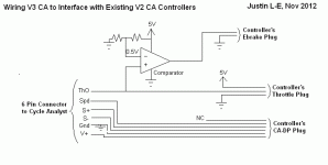
I cut the heatshrink on the CA's plug, pulled out the green wire, and ran it into a throttle connector. Have you considered selling a similar cable adaptor for use on controllers with earlier DP plugs? One side has a 6 pin plug that accepts the V3, the other side breaks the green wire out to a 3-pin throttle connector, and the other 5 wires go to an earlier CA-DP plug.

Yes indeed, in fact even better is that we'll do that including an additional 2-pin wire for your controller's ebrake/regen input as well. The sketch below shows the basic schematic that will allow the CA V3 to interface to all the existing controllers with a V2 CA plug and turn on the regen when you use the brake inputs to the CA, taking advantage of the fact that with ebrake engaged the throttle output goes to 0V, while with the throttle off it just sits at the Min Throttle Output value (typically ~1V):

V3 CA Legacy Controller Wiring.gif

teklektik, thanks for your detailed user guides, it really spoon-fed me the setup, made the new features more accessible, and kept me from posting a dozen or so retrospectively stupid questions.

Huge thanks from me as well, Tekletik's been a real star in this process and I feel like I owe him big-time ;)

However, I am having trouble putting in an rshunt value. Does this look odd to you, or am I just misunderstanding something?

The idea is that you shouldn't be toggling between range modes, that's a one time thing depending on if you are hooking up to a large EV that's dealing in 100's of A, or an ebike dealing in 10's of A. So if your shunt is over 0.9 mOhm (as it will be in any ebike controller), then put in the correct value in the low range mode.

In the past the high range mode wouldn't let you input a shunt greater than 0.99mOhm, but in this firmware I let it so that you could still go up to 9.99 mOhm in high range, but if you then switch to low range it will treat that as 99.9 mOhm and you won't see the first digit. I'll put some proper clamps on the input shunt ranges again so that you can't do this. Main thing to keep in mind is that the Range selection effects much more than just the display (W or kW, and .01A or 0.1A), it determines the entire internal scaling factor used for all the power related variables (ie signed 16 bits = +-32,000, could be seen as +- 320 amps or +- 3200 amps).

-Justin
 
teklektik said:
Justin-
After looking at the new B20 Setup scheme, I see that ThrI->CntrlMode is preference-specific. This is kind of handy but brings up an issue with making Aux->AuxFunct global to control the Preset option - it means that throttle scaling might be lost when changing presets because there is no means to make the limit type of Aux->AuxFunct track a preset-dependent limit set in ThrI->CntrlMode. A solution might be to add a new Aux parameter that is global and leave the Aux limit selection associated with the preferences, perhaps like this:
  • Aux -> Funct = { Off | Limit | Preset } (global)
  • Aux -> Limit = { Amps Lim | Speed Lim| Power Lim | Pas Level } (preset-specific)
Software Updater Failure

That, Teklektik, is a nice work around. It is turning into quite a convoluted setup menu but this change would be fairly clean and and organized.

Using the v1.1 updater I repeated got into a state where the app would report that it was downloading but seemed unable to communicate with the CA, The cursor would just flicker with an hourglass every few seconds and the flash would never proceed. I tried multiple COM ports and restarted the app many times to no avail. I then ran the older not-so-automated version (circa 2012-10-16) and had no difficulty flashing. The 1.1 version had worked previously.
Hmm, when this happened was the CA screen blank and not showing anything (so in bootloader mode?). It might be as you suggest related to a noisy power up sequence or time delayed precharger that results in the CA power cycling after the initial communication. We can try putting in more of a latency between the CA detection and initiating the write sequence as you suggest. I'll get MRVass on it for next update.

ThrO -> Down Ramp Is Global
It looks like ThrO->UpRamp is preference-specific but ThrO->DownRamp is global. No big deal, but it seems a little asymmetric. DownRamp probably isn't as generally useful as UpRamp, but I just thought I'd call this out in case it was accidental...

Nothing ever slips by you does it ;)
This is deliberate and the asymmetry of it pains me a bit too. It's essential for the up-ramp to not be global, as some modes like PAS control without a torque sensor require a slow ramp rate, which you wouldn't want in a throttle mode. However, the ramp down will rarely if ever get used, and if so it's likely more for system reasons than ride preference, so I couldn't see any justification in using up the some of the last bytes of remaining EEPROM to store 3 different instances of a down ramp rate.

I see that the button to enter Setup has been swapped back to the V2 style (left button). I'm sure there are good reasons, but I still think using the Right button is easier (just registering a vote here in case design decisions go democratic ;) )

This was democracy winning but you weren't around to cast the vote! Around the shop here it was driving people crazy to break button pushing habits when switching between the CA2 to CA3, and I figured that was going to be the same for every dealer or regular user down the road too.

Ideally, I'm trying to make it so that you never need to go into the setup menu once things are sorted out for your system, that's part of the motive behind the mode and battery presets. So the fact that it's somewhat more natural to get into setup menu with a right press shouldn't come into play as much. Plus, with the current button system you can still do everything via just a single button interface.

There is an issue with the preset management where PrSt->CrntPrst is not forced to be consistent with PrSt->PresetCnt. The problem is manifest when there is more than one preset and the preset count is reduced causing PrSt->CrntPrst to be left referencing a retired preset (e.g. If Cnt=3, Crnt=3, then set Cnt=1. Crnt will still refer to 3). I might suggest simply forcing PrSt->CrntPreset to "1" with associated data shuffling prior to any value reduction of PrSt->PresetCnt, but you get the drift - just a small bookkeeping oversight.

Yup. You'll notice that this is handled with the battery presets, so if you have battery 'C' selected and then change to only enabling two batteries, it will boot you down to battery 'B'. I just hadn't decided if this was the best way to do it with the mode presets too. These kind of things will be easier to make intuitive behavior for with a PC interface for all the settings, where we could have cells that are greyed out when no longer relevant and such.

It does have some weird effects though: in one instance a combination of meddling with the preset count and changing the current preset using both Setup and the quick-change button shortcut somehow managed to overwrite all my #1 presets with copies of the #2 presets...

The way the code is written and presets are stored this is unlikely (or more like impossible). It would be more likely that you were in a different preset setting than you thought when putting in the values. But yeah, the layout for enabling different #'s of presets and then setting them leaves something to be desired.

Setup Motor Burp
When sequencing through actual setup parameters (not the section headers), my motors bark a bit on leaving each parameter. It's not necessary to actually change anything, just scrolling is enough. This doesn't seem harmful for moderate power bikes like mine, but it's a little unnerving. (Related to throttle kick issue and more noticeable on certain bikes?)

I was wondering if anyone would notice this :). The little bark that you felt is 4 MILLISECONDS of throttle output that can occasionally happen when the CA goes into sleep mode while writing to eeprom! This is a slight consequence to making the throttle output stay at the MinOutput rather than going to 0V when you are in the setup menu so that it won't engage regen in a setup so configured. I noticed it on the oscilloscope (and have it fixed in B21) but didn't think it would make it through the throttle input filter on any controllers.

Thanks as always Tekletik. Hopeful release time for B21 is this Saturday.

We've also got a V3 CA shunt in production now that passes through the throttle and speedo signals from the 6-pin connector. This is especially handy for those doing RC controller interfaces to the CA, since you can repurpose the yellow speedo wire as a 5V line and the green wire becomes the servo pulse signal, and also for using a CA3 on an ebike controller without a Cycle Analyst plug on it.
CA V3 Shunt.gif

-Justin
 
cruzxia said:
Justin

Mode 1 & 2 issue resolved,
I found the issue that was preventing the throttle opening in mode 1. For some reason the start speed in mode 1 had defaulted to 99kph. once I set it back to 0 mode 1 and 2 both worked perfectly.

Dopes, ignore my previous reply then, I hadn't got to this follow-up when I posted it.

I think that you could make the CA learn the voltages at a given speed, and then store them in a look up table, then when you set the max speed to 22kph the throttle will limit at 1.30v as an example. You could enter a speed mapping mode via setup, where the bike accelerates by ramping the voltage up slowly and store the voltages at every 5kph.

In earlier versions of the V3 beta firmware there was actually a term in the setup menu for setting the V/kph motor KV factor for doing exactly this. Effectively giving an open loop type of speed control. I still have space reserved for this in eeprom just haven't made use of it yet.

If you have a really stiff system (so a motor with very low winding resistance and a high amperage motor controller), then it can wind up holding decently uniform speed even under changing loads. But with most ebike motors and especially direct drive hubs, a throttle voltage that gives 30kph on the flats, might slow down to 20kph up a moderate hill and 10kph up a steep hill. You need to dynamically change the throttle setting a fair amount in order to sustain a steady speed.

Using this method would eliminate surging, use less power, and be easier for the user to setup.
Even if you don't use this method to control the speed, once a speed limit is set E.G 20kph, then the throttle should be limited to 1.30v in this case, to prevent over shooting the chosen speed.

It's the right idea, but you'll find even with your bike on a really steep hill you might need 2-3 V to keep up the 20 kph. So the best approach would be for the CA to use the throttle voltage to speed mapping info as the 'first guess' value for the CA's output, which would prevent initial surging, and then tweak it up and down as necessary so that you do eventually hit and maintain the target speed (which is currently done via the Int S Gain setting).
 
justin_le said:
Yes indeed, in fact even better is that we'll do that including an additional 2-pin wire for your controller's ebrake/regen input as well.

Justin

Hi Justin,

any idea when these legacy controller adapter cables will be available ?

my current controller has the CA V2 plug on it.

Jason.
 
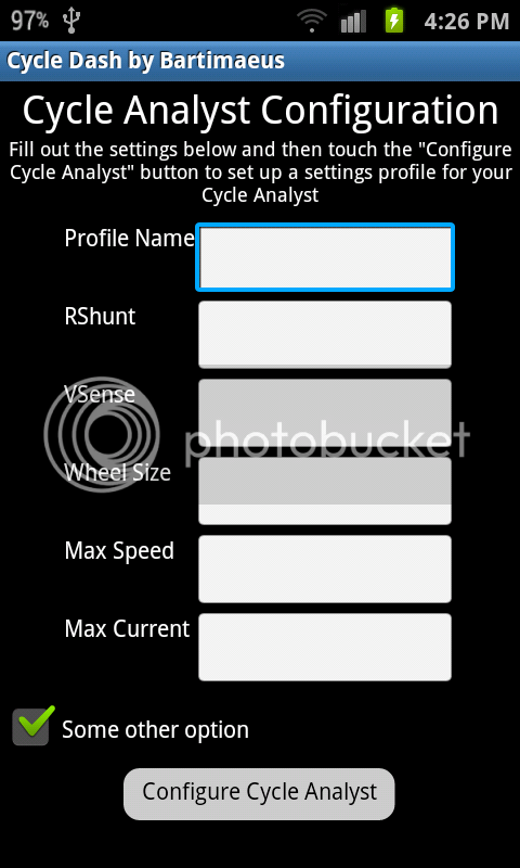
Justin, is there any chance you could add the ability to set up the setting modes from the serial pin? I've been working on an Android App for the cycle analyst, and I was thinking that having that feature would be really handy to have. Here's a screenshot of what I was thinking of, a working version would include all of the settings and not just these ones:
ScreenShot-3.png


The thread for the app is here: http://endless-sphere.com/forums/viewtopic.php?f=2&t=45661

I'd be willing to work with whatever kind of setup you would want to go with. I was thinking that having an ISR for receiving serial that checks for a "enter config" command, and then from there the phone can send each setting one at a time with an id tag in front of it. After the cycle analyst gets the data for a setting it can send a confirmation byte that tells the phone to send the next setting.
 
Bartimaeus said:
I'd be willing to work with whatever kind of setup you would want to go with. I was thinking that having an ISR for receiving serial that checks for a "enter config" command, and then from there the phone can send each setting one at a time with an id tag in front of it. After the cycle analyst gets the data for a setting it can send a confirmation byte that tells the phone to send the next setting.

Hey Bartimaeus, saw your other thread before the reply here. This can all be done. It wasn't something I was planning to work on until early next year, but it might not take that much time to at least have this functionality crudely implemented in the beta code stage, if you are game for the protocol going through a number of revisions before it gets locked into a 'final' state. Everything on the CA is working in limited memory and assembly programming, so using strings as the ID and ASCII numbers will be tricky and might take a while, but if we just have it such that 01 = RShunt, 02 = Amps Limit, 03 = Speed Limit etc. it won't be too difficult. Most of the data is stored as either signed or unsigned 16 bit integers, so you'd have to binary format the data that way. Presuming that's no problem?

-Justin
 
Ha ha, it'll be great to come up with some conversion functions from scratch! I'll have to do some experimenting, are there any inputs that aren't ints? I don't know how the floating point numbers are shown in binary, but i'm sure it isn't too difficult to learn. I've got a really sizable post I've written on the other thread waiting to be submitted, so I'll keep this one short.
 
Justin: If you could do that... epic. What is the current address length of the storage values? Would it be possible to simply reuse those?

Bart: It actually can vary slightly when we're dealing with various languages, aka Java your standard int tends to lend itself to a signed 32 bit integer, and after a quick search a 'short' would map to a signed 16 bit int, and in the .NET world I'd have a ushort to represent the value appropriately, it appears Java doesn't have built in support. Seemingly good article: http://stackoverflow.com/questions/7306825/java-7-unsigned-16-and-64-bit-integers
 
Justin-
In V3B19 there is a new serial data column 'Acc'. What's this new data? :)

  • Code:
     Ah - Amp hour
      V - voltage
      A - Amperes
      S - Speed
      D - Distance
    Deg - Temperature Degrees
    RPM - PAS RPM
     HW - Human Watts
     Nm - Thun Newton-meters
    ThI - Throttle In Voltage
    ThO - Throttle Out Voltage
    Acc - hmmmm - new data! <------------------!!! [EDIT - temporary for this particular beta release]
    Lim - Limit Flag Characters
 
teklektik said:
Justin-
In V3B19 there is a new serial data column 'Acc'. What's this new data? :)

Ha yes, new data, this is your ebike's acceleration in m/s^2. I needed to bring it out when troubleshooting and debugging the speed limit feedback loop, but will probably hide it again since you can derive this fairly easily from the change in speed between adjacent rows.

-Justin
 
Eascen said:
Justin: If you could do that... epic. What is the current address length of the storage values? Would it be possible to simply reuse those?

Yes for sure, the internal address length is just 8 bits for the 256 user eeprom memory locations (of which ~250 are already claimed). This is what the bootloader and related CA PC software will use for writing the data, and so we'll be compiling various memory location tables for each firmware release if these addresses change around as different features get added or removed. But as much as possible I'll try to keep them consistent across updates.

Bart: It actually can vary slightly when we're dealing with various languages, aka Java your standard int tends to lend itself to a signed 32 bit integer, and after a quick search a 'short' would map to a signed 16 bit int, and in the .NET world I'd have a ushort to represent the value appropriately, it appears Java doesn't have built in support. Seemingly good article: http://stackoverflow.com/questions/7306825/java-7-unsigned-16-and-64-bit-integers

I should mention too, there are a few values that are 32 bit signed integers, as well as a number that are 8-bit unsigned. So you'll definitely need to be able to type-cast your variables to the appropriate form with whatever programming language you are using before transmitting out the serial port.

-Justin
 
Justin,

If you include some of this in your next beta, along with the basic docs I'll commit to writing an API for comm in C#, then move a port to Java so it can be moved reused and OSS it. Since my bike is out of commission for a week or two, it'd be a fun interim project to see if we can help promote some community development of an app (which, I may work on but with my ADD I don't want to commit to too much yet). At minimum it'd let us have a basic Windows API/GUI for programming your CA.
 
OK, so good news on this front. It turns out that the current bootloader program does support byte by byte reprogramming of individual memory locations in eeprom rather than just the full block, so it's possible to do this with the existing firmware if you send the ascii character "U" (0x55 in hex) within about 200mS of powering on the device. If the CA sees that, it will reply with the string "CAXX" where XX is the bootloader revision number, and then latch in a bootloader state where you can send commands to read and write the parameter settings. I can very easily change this so that if the character "U" is received even during normal code operation it will go into that state too so that you don't need to do a power cycle.

The protocol is a trimmed down version of that described in AN1157, microchips app-note for a pic24f serial bootloader, adapted for the PIC16F devices:
http://ww1.microchip.com/downloads/en/AppNotes/01157a.pdf

The command 04h is used to read EE data, while the command 05h is used to write data, which are the only two operations of relevance here. It is a little bit convoluted since the protocol uses little endian for the address data, while I've got all the variables stored in big-endian in eeprom, so you'd need to keep those byte orders straight. It also treats all addresses as 24 bits wide and all data as 16 bits, even though in the case of data eeprom both the address and data fields are only 8 bits long. So the result is a lot of unecessary zeros going back and forth.

Eascen said:
Justin,
If you include some of this in your next beta, along with the basic docs I'll commit to writing an API for comm in C#, then move a port to Java so it can be moved reused and OSS it. Since my bike is out of commission for a week or two, it'd be a fun interim project to see if we can help promote some community development of an app (which, I may work on but with my ADD I don't want to commit to too much yet). At minimum it'd let us have a basic Windows API/GUI for programming your CA.

This would be super! I'll work with MRVass to get the full documentation done for the bootloader syntax soon then, and also prepare the memory map for the address and format of each setting parameter. It effectively looks something like this, to write 2 bytes 0x1234 to eeprom at memory locations 6 and 7 you'd need to send

Code:
0x55  0x55  0x05  0x05   0x02   0x06  0x00  0x00  0x12   0x00   0x34   0x00   0x53  0x04
start/sync   DLE  WT_EE  2Bytes ADRL  ADRH  ADRU  Byte1L Byte1H Byte2L Byte2H Cksm  End

If all went well, the CA will then reply with and echo of the command (0x05)
 
Justin,

I figured I would start with attempting to read some data first, before I go attempting to write things. Following the guide above, I've got it into bootloader mode, and have the following being sent:
0x55, 0x55, 0x05, 0x04, 0x01, 0x02, 0x00, 0x00, 0x04
(my assumption would be read 1 byte from mem 2)
To which the response appears somewhat consistent with the documentation except a minor confusion I seem to have about this:
First bits as expected (in decimal):
Code:
85, 85, 5, 4, 1, 2, 0 (eg 0x55, 0x55, 0x05, 0x04, 0x01, 0x02, 0x00)
followed by:
Mem1:
Code:
0, 1, 0, 247, 128, 127, 20, 235??, 64, 0, 254, 48, 255, 0, 255, 64, 191, 153(csum?), 0x04
Mem2:
Code:
0, 0, 0, 247, 128, 127, 20, 235??, 64, 0, 254, 48, 255, 0, 255, 64, 191, 153 (csum?), and lastly 0x04
(ETX) which leaves me with 18 bytes in the response stream, though I requested an LEN of 0x01, I'm receiving 18 response bytes.
Mem3:
Code:
0, 5, 4, 0, 247, 128, 127, 20, 251??, 64, 0, 254, 48, 255, 0, 255, 64, 191, 132 (again, csum?), 0x04.
Mem4: No response
Mem5: No response
Mem6:
Code:
0, 255, 0, 247, 128, 127, 20, 251??, 64, 0, 254, 48, 255, 0, 255, 64, 191, 134 0x04.

Every time I start the analyst, the 235/251 value seems to change (not when booting to loader, but if I accidently let it boot to the app code), which leaves me to believe the checksum on it though I haven't run it through.
Reading 0x02 len for Mem1:
Code:
0, 1, 0, 0, 0, 0, 127, 20, 249??, 64, 0, 254, 48, 255, 0, 255, 64, 191, 1, 0x04
vs 1 len:
Code:
0, 1, 0, 247, 128, 127, 20, 235??, 64, 0, 254, 48, 255, 0, 255, 64, 191, 153, 0x04

Which, provides me consistent enough results to ask the TLDR:
Data and addresses are 8 bits, though the bootloader expects 16/24, which makes sense with the above addresses in your example, but my results seem somewhat inconsistent with my reading. If I'm on the proper track and value 2 (index 1) is actually the value I'm looking for, I'll call it a day and wait for the mapping; though it makes Mem3 look off, If you have a few basic mappings I can use for testing, I can likely get quite a bit further tomorrow :).

Thanks again for supporting this, and I apologize for my lack of low level programming skills, most of my work is done in higher level languages.
 
Back
Top