Thud said:
max amp draw is infinit...... :lol: just won't last long like that.
Of course, it's all question of energy, not amps... :wink:
I see 100 amps under max acceleration on 18 cells (programmed limits on a xie-chang 12-FET, measured with a calibrated CA.) but at full speed the draw is typicly less than 35 amps with a 40-MPH gearing.
The same set up pulls 200 amps thru a castle HV-160 on 12 cells as read on the castle logging software..
Can you give me an idea of how many seconds are we talking about? 100A for 5~30s?
less than 5 seconds in most cases
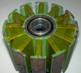
I read something about flux rings, can you supply a photo or some explanation? something to do with lower starting amps and lower Kv...
The actual steel can the magnets reside in is the flux ring. It completes the magnetic circuit in the rotor. There are examples & data that show there is minor improvement available with a slightly thicker can. (not worth making a new one IMHO)
A bit off topic, what awg wire(s) have you used on a CA120-70? Ever rewound a rotomax-150cc?
my current CA120 is wound with 15-awg, I am pretty sure its a 3 wire wind but I forget how many turns. (I think 5 turns)
no experience with the newer ca120's or the rotomax motors.
Regards

") , just finished a schematic, need you guys to double check it so i don't make any errors when i start.
, just finished a schematic, need you guys to double check it so i don't make any errors when i start.