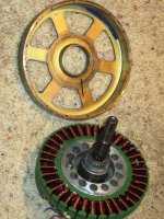
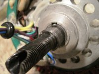
Converting a hubmotor to a middrivemotor

Ah, that helps, and the freewheel inside my hub motor IS backwards.

All that kind of gets back to the point of how to attach freewheel sprockets to the motor shafts. Seems like if you were going to use threaded freewheels, they'd both have to be lefties.

A splined adaptor would allow placing freewheels in either direction. Harder to make though.

Another possible approach would be to use a non-freewheeling sprocket on the motor and use a jackshaft that has freewheels.
 
For an application like Crossbreaks where the motor becomes a jackshaft, you really only need a freewheel on the left side. By using a freewheel adapter, you can put it on either way so no need for a left hand thread FW. I don't know if that's clear or not what I'm saying, basically you can put the FW on the adapter first and then the the whole assembly on the axle backwards if you need to. That works fine.

The other thing I thought of tonight is just getting some 5/8" stainless round stock, drill it in the center and tap it for threads to screw onto the axle. Secure it on the axle using DP420 and it should never come off again. Then you have a perfect 5/8" shaft coming off the motor for using whatever FW adapter you want to. Nice, cheap, easy to make, and should be as solid as the rock of Gibraltar. 8)
 
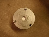
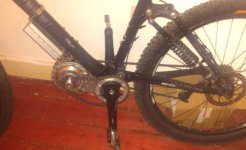
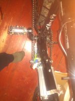
this pic is somewhat misleading since the cables of a MAC/BMC/Puma are on the left side, also the torque arms/dogs for the drive sprocket are missing. Just screwed on my selfmade (shimano hyperglide to 12mm flattened hub axle ) adaptor to make a pic for you. The drive is not finished yet. It sucks since my rear suspension does not like the motor (or jackshaft, it's the same on this one) position, the suspension collapses on full throttle like a 2-link FS does. Il'l take it out of the frame triangle and install it in front of the BB like GNGV2 :?

OK I used the second post of this topic as summarize
 
StudEbiker said:
For an application like Crossbreaks where the motor becomes a jackshaft, you really only need a freewheel on the left side. By using a freewheel adapter, you can put it on either way so no need for a left hand thread FW. I don't know if that's clear or not what I'm saying, basically you can put the FW on the adapter first and then the the whole assembly on the axle backwards if you need to. That works fine.

Ah, that makes sense. I didn't think of that.

crossbreak said:
There is a build in freewheel in the MAC. To use the MAC backwards you would have to lock that one with a small weld.

It may be possible to remove the freewheel and flip it over and reinstall it to reverse its direction.

The timing on a BMC is not neutral, but it is possible to make it run in either direction. You may need to hunt to find the right hall/phase combination. I really wish they were neutral timed. Seems possible to do, but is difficult in practice.
 
BlackArrow said:
Hi,


Well in my case I have seen many post about a clutch fail in a MAC motor then I preferred to weld it or to upgrade it for a one way industrial bearing.

Chinese bearing are sometime very cheap and have hard time handling too much power, good day!
Black Arrow

Black Arrow,

I too had read some posts and seen some pictures of MAC and BMC clutch failures. Cellman had just revised the EM3ev website to include some new items including a new clutch and gear assembly for MAC motors when I was ready to order mine. I ordered a new clutch and gear assembly when I ordered my motor. When I received the order I was VERY impressed with the new clutch. It looks much tougher. The failures I had read about in older clutches was that the outer race for the sprag bearing separated from the plant gear carrier. In the new clutch the sprag clutch outer race IS the planet gear carrier. Nothing to here to separate buddy, move on :lol: Unfortunately my motor, though new, did not contain the new clutch assembly, but it does now! I suspect all the MAC motors shipping now probably have the new clutch assemblies in them now.

PC180460.JPG


In all honesty the old clutch was probably adequate for the average Chinese Commuter. If you are not Hot Rodding the $#!t out of it :roll:
Glad to get the improvements though :mrgreen:

bØb
 
Hi Black Arrow,
this would be an expensive setup. A belt drive will weight more for the same power and it will be larger. Why do you want to throw away something that is already perfect?

If you dislike the clutch just weld it and use your own freewheel on the outside ;)

fechter said:
It may be possible to remove the freewheel and flip it over and reinstall it to reverse its direction.
With my bafangs this is not possible. Also it would not make much sense, since then the heat sink would then be on the right, where space is already limited.
 
BlackArrow said:
Hi B0b,

Thank you I'm seriously thinking to uncork my Mac motor from its original planetary geared drive system.I will replace the sun gear on the MAC for belt gear to make something that look closer to the GNG drive system if the system box is open.

But with a more torquey belt for more power output that the gears can handle. This system will be in an enclosed box to protect it against debris, dust and water, to make at the end a silent, light and small mid-drive unit.

It's about the main idea I have in mind, good day!
Black Arrow

Hi BlackArrow,

I understand that you want to remove the planetary gear reduction from a MAC geared hub motor. If you would start another topic like "De-Gearing the MAC", I would be happy to share what would be a simple and killer method to do this. I just don't want to hijack this thread again. The resulting motor would be square (easy to mount) and at least 1-3/4" thinner than a MAC geared hub. Could even be air cooled if you want, since there are no gears to protect from grit. The motor would have only 1/5 the torque as a hub motor or 1/6 the torque of the hub motor converted to shaft drive. You would end up with a low~med speed high torque motor.

PC010438.JPG

bØb
 
The MAC will get horribly inefficient pushing more than 2000Watt input. Calculated a lot. This was on page 5 or so. The GNG has more power.Read the second post also
The only advantage I see is that it is narrow. With a belt on it is not narrow anymore. Planets are ~10mm wide belt would be at least 15mm :(

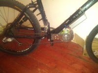
this is what my bike looks like ATM BTW, did not make any progress last sunday. next one i wont also, guess this will go on next year.
 

Attachments

  • christmax2012_1.jpg
    christmax2012_1.jpg
    97.3 KB · Views: 2,620
  • christmax2012_2.jpg
    christmax2012_2.jpg
    96.2 KB · Views: 2,620
  • christmax2012_3.jpg
    christmax2012_3.jpg
    118.9 KB · Views: 2,620
crossbreak said:
BTW, did not make any progress last sunday. next one i wont also, guess this will go on next year.
I am trying to be on the road before new years. Christmas parties , kids off school and family visits have made this an aggressive goal.
 
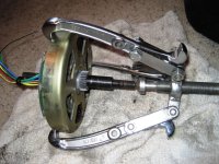
I am attempting to remove the rotor from my Ezee motor and I want to make sure I'm doing this correctly. I searched high and low for pictures of doing this part correctly and couldn't find any.

Is this the way I am supposed to do it?

002.JPG003.JPG

I put it on like this and tried some pressure, but it didn't come off "easy" like the gears did. Crossbreak warned in an earlier post not to force this so I want to make sure I am am correct before I apply any more pressure.
 
That looks right. I think you need to remove a circlip from the rotor first though. Once you get the rotor about a cm past the stator, the force will be much less. It's easy to bend the rotor spokes. The magnets should be the only thing you're fighting against.
rotor clip.jpg
 
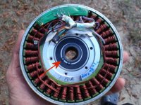
I don't think I would proceed with the gear puller from what I can see. Can you post a wider shot of 003.jpg? You don't want to put any pressure on any of the magnets. You can pop them loose or chip them very easily. If you damage the coating on the magnets, they will corrode and fail. Is there a snap ring on the axle in front of the sun gear? The rotor that the magnets are glued into is not very stout and would be easy to bend. Why do you want to take it off?

bØb
 
fechter said:
That looks right. I think you need to remove a circlip from the rotor first though. Once you get the rotor about a cm past the stator, the force will be much less. It's easy to bend the rotor spokes. The magnets should be the only thing you're fighting against.

fechter,
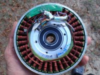
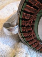
You are looking at a different motor in the picture here. That is a picture of my MAC in my hand. Yes you do remove the circlip first :) After that I put a 1/2" nut on top of the shaft and put the cap back on with 2 screws to push the rotor off the stator a short distance to measure the thickness of the laminations. I never took the rotor all the way off. No need to.
I'm pretty sure StudEbiker's motor is different.

bØb
 
Well, it looks like I frocked this motor up! :oops:

Damn it!

Haste makes waste.

As for why I needed to take this off, I thought I need to do this to get the axle out to reduce it's diameter to turn freely.

Boy I'm pissed.

I saw no other clips on here (opposite side shown in pic7), so I still don't understand why this happened. :evil:
 

Attachments

  • 006.JPG
    006.JPG
    87.1 KB · Views: 2,514
  • 007.JPG
    007.JPG
    53.6 KB · Views: 2,514
Can you turn the sun gear with your fingers?

bØb
 
Back
Top