XPD: open-source keywin e-bike lab replacement

alsmith said:
Probably silly, but my Lyen has a reverse speed that can be set as well as the 3 forward. ????
Nope. X3 is for reverse, even on the Mark III boards. :)

Reverse is suppose to be up to 35% of Forward speed. Too bad we can use it as a variable regen-brake :wink:

~KF
 
electraflyit said:
Hi,
I have EB2## and EB3## controllers.
Does anyone know what 'speed 4' does in the EB3## software, or how it interacts with speed 1,2,3 & SL?
I have all the speeds( 3 + SL)working in the EB2## software but am having problems working out the EB3## settings
thanks Eddie


You can also use a push button as speedswitch and cycle through speed 1-2-3 (speed switch cycle 3) or 1-2-3-4 if you choose that (cycle 4).
 
Good morning.

Ok got this 12FET Infineon from Hyena.. rather than bugging him with endless questions I thought I would post here.

I cannot program the controller. The board has EB212-AS-1 printed on it, it has IRFB4110 FETs.
there are pictures on the forum relating to my efforts to find a solution.
http://www.endless-sphere.com/forum...05&hilit=infineon+programming+header&start=45
http://98.131.176.65/endless-sphere/EB212-AS-1.jpg
http://www.endless-sphere.com/forum...194656&hilit=header+programming+EB212#p194656
and of course the link to the Infineon "doc" http://www.endless-sphere.com/forums/viewtopic.php?f=2&t=19446

My picture: 20121027_091701 [800x600].jpg
20121027_100748 [800x600].jpg
20121027_100731 [800x600].jpg
From left to right I have tried:
?RST - wired to +5v through a momentary push button.
5V - 5V from USB -TTL adapter
GND - GND from USB - TTL adapter
Rx - Wired to USB - TTL Tx
Tx - Wired to USB - TTL Rx
Open

So the connection above is what I found in one of the posts However, it makes more sense for me that the RST pin would be on the right side (next to the res1 resistor) So I am about to go off and try soldering that to the momentary 5V button. My problem is that there are other versions of the board in other forums posts that have the RES1 resistor on the other side of the header (LEFT) but then connect a wire which seems to me intended as RST to the right side of the header opposite the resistor.

Tried also with no success
open
5V
GND
Rx also tried swapped to Tx
Tx also tried swapped to Rx.
RST

I also tried swapping Tx and Rx, and repeating the above steps. at one stage I thought it succeeded as it said "uploading" briefly but this was not repeatable.

My process is:
Start software
Plug in USB-TTL adapter (5V disconnected)
press transmit
Connect 5V AND/OR Press RST momentary button
wait...wait...wait...give up waiting.
cancel
try every other combination, etc

As a note, I have jumpered Tx and Rx on the USB - TTL adapter to test for function. Did this at 9600 using putty terminal and it worked fine.

Any opinions? I have tried the XPD software and also the parameter designer, operating system is Windows Vista 64bit, I am running whatever I can as admin, and have registered the coms drivers as instructed so I believe the software is functional.

Andy
 
By using the protocol information which anpaza has kindly posted, it should be fairly simple to use an arduino with a screen and buttons to program these controllers on the fly without using a computer.

I don't currently have a spare ardiuno, or spare controller to test my theory, but when my post-battery-upgrade high has faded I'll take a look at updating this thread with some results :D
 
gwhy! said:
not so good on a bike :mrgreen:

wht do you mean..just great on a bike..as security option. I recently had two normal bikes stolen from the house. I had thought of building up a sacrificial e-bike, set up with full speed reverse, and leave it (hidden and locked out side the house) where the other two bikes were stolen from. Would jsut love to see some..Bas***d come along, cut the lock again, jump on it, and open the throttle wide for a quick get away :twisted: ..maybe something sharp on the handle bars for the added effect :twisted:
 
FWIW, I often leave CB2 in reverse when it's parked; it appears to be a full-power reverse mode, in an older unprogrammable 18FET. ;) Should someone come along and plug things back in (also leave battery and stuff unplugged) and manage to cut the lock, they should ahve an interesting surprise. :lol:

Typically no one messes with the big ugly thing, but someday someone will, I'm sure.
 
Great job on this. I finally got around to downloading this new program and got it to run on my laptop.

Note: For my EB312, using the EB312 board setting, set amps to 1/2 of desired peak. I'm not sure if that was said here. I set mine to 13a battery, 30a phase for a nice gradual increase in power as I get up to speed. It tames the Mac to be more manageable and I bet increases efficiency. So that's 26amps peak I am running. On the old software, it didn't matter what I set phase to, it always shot off the line full blast.
 
Just released version 0.3.2.
As always, download from
http://xpd.berlios.de
or directly from
https://developer.berlios.de/project/showfiles.php?group_id=12389

Changes wrt 0.3.1:
  • Added support for EB318/CellMan controller
  • Fixed a bug in EB312/CellMan and EB218/Crystalyte profiles
  • Changed the description of PAS Mode for Infineon 2, thanks to "cybershot"
 
Nice.... this is the one I tell everyone to use now.
Good work.

-methods
 
johnamon said:
By using the protocol information which anpaza has kindly posted, it should be fairly simple to use an arduino with a screen and buttons to program these controllers on the fly without using a computer.

I don't currently have a spare ardiuno, or spare controller to test my theory, but when my post-battery-upgrade high has faded I'll take a look at updating this thread with some results :D

I have actually done this already, though I didn't build a cable and test it programming a controller yet, there will be some bugs. Too many projects. Used an Arduino board and an LCD shield.
 
Hi guys I cannot program my controller, it just sits there saying "waiting for controller ready"

I'm using a Keywin eb306 board, and I have not managed to program it with any software yet.

Here is a photo of the back of my board, I have only hooked up the gnd, +5v, RX and TX pins.

fxk3kl.jpg


There are SLK1 and SLK2 pins, are these needed for programming at all?

Also just to check I'm wiring it up ok, RXD goes to RXD and TXD goes to TXD on my USB to ttl board?

Thanks
 
Not seen or do not recall seeing the SLK pins before...but

RX goes to RX and TX to RX.
RX is receive and TX is transmit. , so they have to be wired one to the other.

there are various ways of wiring the cable also. some cables have jumper, .

A search of the forum..using Google Advance search is best.. I have the info somewhere at home..but I am away in different country for a few days.

Also you often need one of the leads...ground possibly to have a momentary switch, and you need to break/ make the contact while the software is attempting to send data

I'll search my PM's now for further data
 
also remember some controller MCU's just can not be programmed. they are one time EEPROMS...sorry can't think what the proper name for them is. Often marked with a spot of paint or ..at least that is what I have been told


you could try e-mailing him directly
ecrazyman at gmail.com
 
HypnoToad said:


Yea, you need to show your wiring a little better.

RX to TX
TX to RX

There is power and enable
Enable must be toggled to start the download. The chip will only flash on power-up because the programming pins are multiplexed. This means that after power up the RX and TX pins have different applications. I cant remember which they are - but if you have a certain thing plugged in the controller wont program either. Was it the 3spd switch? You can follow the traces on the board to identify.

My controllers wont program with reverse enabled either

My controllers are very fussy about which program you try to use

I stat with the controller off
I select the code I want to run
plug in
when everything is ready I toggle the button and the download should take less than a second

Yes - there are non-programmable chips out there too. Tons of them.

Disconnect all accessories
Take clear pictures of your USB dongle, the wiring, the board, and your button - so we can see it all in one picture

-methods
 
NeilP said:
also remember some controller MCU's just can not be programmed. they are one time EEPROMS...sorry can't think what the proper name for them is. Often marked with a spot of paint or ..at least that is what I have been told


you could try e-mailing him directly
ecrazyman at gmail.com
Thanks, I have emailed him but have yet to get a reply. He usually takes a day or two to respond in my experience, but I'm pretty sure this controller I have is one of the reprogramable types. I'm 99% sure it's an Infineon based controller.

I think I had my TX and RX pins around the wrong way also, so today I'm going to have another go.

Ill try searching some more on the forum, as there are different boards and I have yet to find any with the SLK pins on them.

methods said:
Yea, you need to show your wiring a little better.

RX to TX
TX to RX

There is power and enable
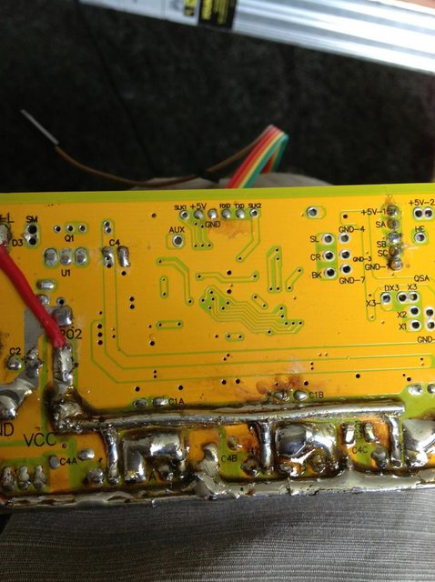
Ok, on my controller I have 6 pins in a row, and on the PCB the pins are marked: SLK1, +5V, GND, RXD, TXD, SLK2

On my USB to TTL adaptor I have 6 pins also, marked: RST, 3V3, 5v, TXD, RXD, GND

Right now I have it hooked up like this:

Controller -> USB to TTL adaptor
GND -> GND
+5v -> 5v
RXD -> TXD
TXD -> RXD

I cannot find any pins marked Enable at all, unless it's one of the SLK pins?
methods said:
Enable must be toggled to start the download. The chip will only flash on power-up because the programming pins are multiplexed. This means that after power up the RX and TX pins have different applications. I cant remember which they are - but if you have a certain thing plugged in the controller wont program either. Was it the 3spd switch? You can follow the traces on the board to identify.

My controllers wont program with reverse enabled either

My controllers are very fussy about which program you try to use

I stat with the controller off
I select the code I want to run
plug in
when everything is ready I toggle the button and the download should take less than a second

Yes - there are non-programmable chips out there too. Tons of them.

Disconnect all accessories
Take clear pictures of your USB dongle, the wiring, the board, and your button - so we can see it all in one picture

-methods
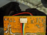
Ok, I have everything apart from the 4 pins on the controller unhooked. No throttle connected, no motor, as I have yet to install this controller on the bike.

Here is a pic of my setup, click on the pic for a larger version:


green is GND
red is 5v
yellow and orange are RXD and TXD

Now I have no button on my cable, can I ask what the button does? Does it connect the enable pin to 5v? If so I can add this is I know what pin to use as my enable pin.

Also I'm not 100% sure that my USB to TTL adaptor works, right now I'm looking on google how to do a loopback test.
 
https://docs.google.com/viewer?a=v&pid=sites&srcid=ZGVmYXVsdGRvbWFpbnxzaGVsYnllbGVjdHJvfGd4OjQ3NzE0NmE3ZWY5OWVmNDQ&pli=1


http://endless-sphere.com/forums/viewtopic.php?f=16&t=7361

Sending this from mobile, not home. Back home in a few hours

Not sure if the google doc link will work.
Maybe no useful info on thete, but all I can do till I get home
 
I got on to a PC in the office before I launch for home, and checked the google doc...go down to page 7.
poor quality pic, but it appears to be the 5v line that is switched.

BUT...two of the pins also need jumpering together. I was hoping someone else would have got in before me with the info, if not, then you wil just have to wait till I get home, but for at destination at moment, so not going anywhere.. sorry, best I can do without my own computer...
 
No problem, I'm happy to wait and I appreciate your help here. The google docs link works fine, it does look like the 5v line is being switched there but by the looks of it there is no enable pin?

I tried a loopback test and my USB adaptor works ok, so that's one less thing to worry about.

I found some info in this thread, that features a sunplus controller with 6 pins near the mcu, similar to my unit:

http://endless-sphere.com/forums/viewtopic.php?f=2&t=31519


zEEz said:
I got a chat via email to ecrazyman: he is very nice and spot on.
For anybody interested, this controller is programmable with his program and also XPD:

regarding the pinout of the more recent 6 pin connector, this is what you need:

programming only need 5 wires ,from the pcb top and left to right :
1, connect to +5v on USB to TTL cable side (do not connect them on PCB)
2, +5v
3, gnd
4, RXD (connect to cable TX)
5, TXD (connect to cable RX)
6, empty

have fun!

So by the looks of it my enable pin is pin1, the pin right next to the 5v pin.

What I'm going to do now is modify my cable by putting a switch inline, and make it so it switches the 5v line and the enable pin on when I hit the switch.

Does this sound correct?

Thanks.
 
I know that on the cable I had for a EB3xx controller, it came with a short extension. The extension had a loop connector, connecting pin 1 to pin5. but till I get to see the cable, can't tell you what those pins actually are.

I found these two pictures, and I think from memory the link is feeding 5volt to the yellow pin.
This is not needed on an EB2 board, but is on EB3.
if you have a 3 speed switch, make sure it is disconnected..or jsut in the middle position.
As said earlier..probably just easier to disconnect everything..some times good to disconnect batttery with controller still powered ON and CA throttle etc still plugged in. In this way, all power is drained from the caps on the board..so it is powered down fully with no charge on the board anywhere
 

Attachments

  • EB3xx%20connection.JPG
    EB3xx%20connection.JPG
    67.4 KB · Views: 4,989
Thanks, I tried using the switched +5v feed on to the very right hand pin (where the yellow wire goes in your photo), but I still cannot get it to program unfortunately.

I did come across this thread which seems to have more than wiring configuration for this board:

http://endless-sphere.com/forums/viewtopic.php?f=2&t=45545&p=664427

It seems everyone apart from Animalector managed to program their controller, and would I be right in assuming different revisions of this EB306 board have differently marked pads?

Mine says EB306-A-5 on the PCB, while Crumly in the thread linked has a EB306-C-6

If it's any help I ordered this controller from Keywin in August which may explain why mine is a different revision?

I did notice that Animalector also posted in this thread, did you ever manage to program your board and if so how did you connect it up?

EDIT: Just found this thread, seems someone else has a board with SLK1 and SLK2 connections:

http://endless-sphere.com/forums/viewtopic.php?f=30&t=41724


Thanks.
 
All of this information has been discussed ad nauseum on the forum over the last few years - so searching should very quickly get you the answers you seek. If you go to the Technical Reference Area there are tons of threads that spell out all of the details of programming these infineon controllers. User Knuckles and all of the "Infineon for dummies" type threads are where you should start

Yes - the pin next to 5V needs to be jumpered to the 5V

The point of the button is to power cycle the chip. You can put the button on ground or power - does not matter - just make sure that pressing the button kills power to the uController and releasing it applies power. This is how you trigger an upload.

Also - realize that the moment you release this button a surge of current will need to be supplied. The 5V rail will sag as all the bypass caps around the chip are powered up. IF this surge takes too long you will get a brown-out, or any of a dozen other undesirable conditions. In the past I have had to modify TTL converters to deal with this inrush current. The way I did it on the last one was cutting the 5V line and installing a current limiting resistor. In my case the TTL Converter was crashing because when I hooked up to the Infineon the inrush was too great - so I slowed the inrush and that did it.

Anyway.... guys like Lyen sell these programmers for like $9. THey already have a button, are known to work, and have a connector on the other side that is plug and play with the controllers. I would buy one of those - or look up pictures of it and copy the design. Just remember that some TTL converters may have issues with all the inrush current at the moment of connection (button release)

It is a hack way to do it

Back in the day we used to just "poke" the 5 pin connector into the controller :)

-methods
 
Thanks for the updated software. Working well.

I had trouble for a period where the values I entered in the software would produce different values or failure to operate for the controller. I have decided that the issue was that I had several parameter designers loaded, 116, lyen mk 2 and XPD. Would seem that the messages were getting scrambled in translation to the controller.
After scrubbing my PC and loading on only xpd everything is sweet again.

So just a warning that having multiple programing programs loaded may interfere with each other and cause incorrect programming of the controllers.
 
I have a button with 3 wires allowing me to wire it up so it either closes or opens the connections.

It turns out I had it wired up incorrectly the first time, as I originally had it to the button would make as opposed to break the connection.

I have now rewired it but it still doesn't seem to program at all.

I've ordered another USB to TTL adaptor now as people on here seem to have success with the prolific chipset based units. I've also tried another PC, running Vista instead of XP, both 32 bit. I haven't tried Linux yet but would this be worth a shot?

If this doesn't work I'll order one of the cables from Lyen, I was hoping to have reprogrammed by now, but if it doesn't work then I may resort to the resistor mod as I only need to change the LVC by 5 volts or so.

I'll keep searching the forums, there is a lot of info on here, but half the battle sometimes can be searching for relevant info.
 
Just to let know you know I managed to get XPD to flash in the end.

After trying 2 dffferent computers, both Ubuntu and windows, eventually my 2nd USB to TTL adaptor arrived and it flashed first time.

So if anyone is having any programming issues, try a different USB to TTL adaptor, they're so cheap and I found the prolific Chipset one worked for me.

Thanks for your patience and assistance, now to play around its various configs.

I did notice that there is no default profile for the EB306 board included, so I've used a version of the EB312 profile with reduced battery current, and once I've installed the controller on the bike I'll see how well it works. :)
 
Back
Top