Cycle Analyst V3 preview and first beta release

A few folks have downloaded the Printable Setup Notes (file: CaV3SetupNotes_20130113_1610.pdf) over the last day or so. There was some funky duplication of steps in the throttle setup section that has been corrected. The revised edition has been re-posted -- please download again. Sorry about that...

Also - apologies for the generally crappy quality of the PDF when printed - the file is from an image, not generated from text, so there can be a lot of artifacting around the 'text' on pages with images. Terrible for a resume but good enough for the shop... :)
 
justin wrote:

I haven't implemented it yet, but what I will soon do is make it so that the Cycle Analyst computes the battery resistance in real time based on how it sees the voltage change with changing currents. That way you'll be able to directly read out the battery's resistance from the CA, which is an an interesting characteristic to watch to understand how your battery is ageing and how it responds to different temperatures.

is this still in development? or implemented? i ask because i can't connect the ca to a working bike atm, but would like to test my battery's IR. if this is already implemented, i would build a test environment.
 
lollandster said:
European laws don't allow "throttle only" use so an option for selecting "throttle input only with PAS" and/or "Ignore throttle input" would be very useful. Preferably this would also be dependent on the mode select so you can have a legal mode and a off-road mode also for Europeans (I believe Americans can have a off-road/legal mode with the current firmware because they only need to limit speed and power to make it legal).
it's not the same all over europe. in AUSTRIA it's allowed. throttle only is ok. no PAS needed. and power limit is 600w.
sometimes we are lucky. but still paying 50% income tax :(
 
teklektik said:
Also - apologies for the generally crappy quality of the PDF when printed - the file is from an image, not generated from text, so there can be a lot of artifacting around the 'text' on pages with images. Terrible for a resume but good enough for the shop... :)
looked strange. yes. i thought my printer was broken :) but i didn't really care. the information included would have justified any text/picture quality. thanks for your work!
 
izeman said:
justin said:
I haven't implemented it yet, but what I will soon do is make it so that the Cycle Analyst computes the battery resistance in real time...
is this still in development? or implemented?
Yes - it lives! This computed value can be found on sceen (10), two left of the main display. See '5. Console Operation' in the Setup Notes.
 
teklektik said:
izeman said:
justin said:
I haven't implemented it yet, but what I will soon do is make it so that the Cycle Analyst computes the battery resistance in real time...
is this still in development? or implemented?
Yes - it lives! This computed value can be found on sceen (10), two left of the main display. See '5. Console Operation' in the Setup Notes.
now that you say that i can see a difference in the setup guide i used, and my CA. i did NOT enter a IR value, and i guess i can't either. but i think those 0.199Ohm are just a rough first guess, because this value can't be calculated by the CA w/o load. correct?
 
Late Breaking Reature Request
Justin,
Would it be possible to make the following modification: In the Throttle Output settings - IF the user selects R/C Pulse, THEN re-calibrate the range for UpRamp and DownRamp. With large reductions in the range of 20:1 between motor and wheel axle, most of the range of these ramp settings (say from 010 to 999) are essentially meaningless. I've been tweaking these settings on my two RC drive bikes lately, and I find that setting of 1, 2 or 3 are the only settings I personally can feel a difference with. This in itself is not a problem - but on the one bike, "1" is too mild and "2" is too strong, and on the other bike "2" is too mild, and "3" too strong.

If the sensitivity of this 000-999 range can be "enhanced" based on the choice of R/C Pulse - perhaps made "ten times as sensitive", I'd have a range of 001 through about 030 to work with instead of 001 through 003.

I have an admittedly small sample set! Two bikes, three CAv3's. Can anyone else using CAv3 with RC drive weigh in on their experience?
 
izeman said:
i did NOT enter a IR value, and i guess i can't either. but i think those 0.199Ohm are just a rough first guess, because this value can't be calculated by the CA w/o load. correct?
I believe that to be the case, but Justin will need to fill in the details on this one.
 
How to connect a 5V PAS sensor to CAv3 ? There is only a 10V cable.

What high power controllers (>5kw) are compatible with CA-DPS or can self moded for it?


:twisted:
 
bio said:
How to connect a 5V PAS sensor to CAv3 ? There is only a 10V cable.
  • If you have a simple 2-wire switch-closure type sensor, hook it between the PAS input and Gnd pins of the PAS connector.
  • If you have a 3-wire hall type, use the PAS input and Gnd pins on the PAS connector. Then, you can either:
    1. Pick up 5v from the AUX Pot connector, or
    2. Open the CA case and move the white 10v THUN wire to either of the nearby +5v pads (throttle or AUX Pot), allowing you to use the (formerly) 10v pin on the PAS connector for 5v power.
bio said:
What high power controllers (>5kw) are compatible with CA-DPS or can self moded for it?
Since you are using a CA-DPS, you are using a wheel pickup for the speedo signal, so you need only be able to pick up (+), (-), and the two shunt connections. That pretty much opens the field to any controller that isn't potted. Email the vendor and ask if the controller has a CA-DP plug (used to be know as 'Drainbrain' connector - early name of CA). Or, buy the external shunt.
 
teklektik said:
bio said:
How to connect a 5V PAS sensor to CAv3 ? There is only a 10V cable.
  • If you have a simple 2-wire switch-closure type sensor, hook it between the PAS input and Gnd pins of the PAS connector.
  • If you have a 3-wire hall type, use the PAS input and Gnd pins on the PAS connector. Then, you can either:
    1. Pick up 5v from the AUX Pot connector, or
    2. Open the CA case and move the white 10v THUN wire to either of the nearby +5v pads (throttle or AUX Pot), allowing you to use the (formerly) 10v pin on the PAS connector for 5v power.
bio said:
What high power controllers (>5kw) are compatible with CA-DPS or can self moded for it?
Since you are using a CA-DPS, you are using a wheel pickup for the speedo signal, so you need only be able to pick up (+), (-), and the two shunt connections. That pretty much opens the field to any controller that isn't potted. Email the vendor and ask if the controller has a CA-DP plug (used to be know as 'Drainbrain' connector - early name of CA). Or, buy the external shunt.

Its a 3-wire hall type.
I have picked 5v from throttle and now it works, thanks.

Sorry i mixed up CA-DPS with CA-DP plug. I have normal CAv3 with hall speedo pickup with the external shunt but i want more than 50A continous for hill climb.
How long can the external shunt take the peak 100A @ 60V ? The 50A continous and 100A peak irritates me becouse no V is given should be written can take ?KW continous ?KW peak
How much is the maximum V the external shunt can be used?
 
bio said:
Sorry i mixed up CA-DPS with CA-DP plug. I have normal CAv3 with hall speedo pickup with the external shunt but i want more than 50A continous for hill climb.
How long can the external shunt take the peak 100A @ 60V?
This will need an answer on the CA shunt from Justin. If you are in a hurry email Grin Tech. Sounds like you may want to add a CA-DP plug to your controller. This is pretty simple since you don't need to add the diode, etc that was needed for the V2 - you can just pick up the throttle directly for CA-DP pin 6.

bio said:
The 50A continous and 100A peak irritates me becouse no V is given should be written can take ?KW continous ?KW peak
How much is the maximum V the external shunt can be used?
The red (+) wire is a pass-through - it's only there to pick up Vbatt to run the CA, so it plays no role at all. The voltage (regarding power rating) is only what develops across the shunt resistance in the black (-) wire. If you really want to know the shunt wattage you can trivially calculate it from the current limit (50A) and the resistance (1 mOhm) but the exact value is really of no consequence - the Amp rating is all you need to know.
 
teklektik said:
bio said:
Sorry i mixed up CA-DPS with CA-DP plug. I have normal CAv3 with hall speedo pickup with the external shunt but i want more than 50A continous for hill climb.
How long can the external shunt take the peak 100A @ 60V?
This will need an answer on the CA shunt from Justin. If you are in a hurry email Grin Tech. Sounds like you may want to add a CA-DP plug to your controller. This is pretty simple since you don't need to add the diode, etc that was needed for the V2 - you can just pick up the throttle directly for CA-DP pin 6.

bio said:
The 50A continous and 100A peak irritates me becouse no V is given should be written can take ?KW continous ?KW peak
How much is the maximum V the external shunt can be used?
The red (+) wire is a pass-through - it's only there to pick up Vbatt to run the CA, so it plays no role at all. The voltage (regarding power rating) is only what develops across the shunt resistance in the black (-) wire. If you really want to know the shunt wattage you can trivially calculate it from the current limit (50A) and the resistance (1 mOhm) but the exact value is really of no consequence - the Amp rating is all you need to know.

Ok now i understand i make than a CA-DP plug with other shunt.

How can see what firmware version my CA currently has ?
 
teklektik said:
The version is displayed on the power-up splash screen.

lol yeah wow :oops:
I blame the precharge resistor from my test setup i must had my eyes on :roll:
 
I tried flashing with a Keywin programmer. These are the dongles that have the board in the USB housing, a button out on the end for initiating, and a 5 pin connector for the Infineon controllers. Same as what you may have gotten from Lyen (since he gets them from Keywin :wink: )

Anyway - over and over I errored out for bad connection. Finally I desoldered all of the wiring and made a very short 3.5mm dongle and that worked perfect.

Tip of the plug goes to TX on the TTL dongle
Ring goes to RX
Shield goes to ground

The TX line on the CA will put out a pulsed 5V signal (another way to find it) - hook the pulsing one up to RX on the dongle.

You know you have the wiring right (even if it wont program) when the programming software recognizes that a CA is hooked up. If you can get to that stage and it still wont program then you need to clean up your wiring. Just de-solder all of the cabling and directly solder a short phono lead to the board.
,
WARNING: After failing to program my CA was bricked (as far as I could tell). The screen stayed blank after several power cycles - so if you decide to program then you must commit and get it working. Once I got a proper cable rigged up - of course it became un-bricked. If you are in doubt - just buy a plug and play programmer from Ebikes.ca.

-methods

Key words:
Bricked
Lyen programmer
Keywin programmer
TTL Converter not working
UART TTL programmer errors
Flashing not working
programming error
flashing error

P.S. I have done a lot of 9600 baud programming with every manor of jacked-up, unshielded cable. I think a time-out is set too tight somewhere in the flashing software as the first cable I built should have worked. It was really fussy - too fussy for something *not* to have been wrong. I presume all testing and tuning was done with an ebikes.ca programmer.
 
I have tryed to install a 0.25mOhm shunt but seems like i have made mistake changing to high range now i cant get it display 0.25mOhm.
Even in low or high i tryed all from 2500 0250 0025.
On page 57 justin has sayed that this will be fixed in v3B22 but how long till release?

Have i now to flash to v3B19 and write for Rshunt 0.25 in high than reflash v3B21 ?
 
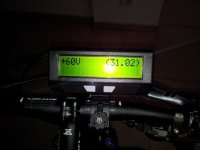
Today I received my new Cycle Analyst v3. Before I had the old version v2.3. It was necessary to change the Cycle Analysts because I want to use the Thun Torque Kit in future.

Sadly the new Cycle Analyst doesn't work well. When connecting to the battery, I have the message "V3 Calibr" instead of s.th. like "V3 Beta20" or "V3 Beta21".

After the starting procedure there isn't the normal display of voltage, speed, Watt and so on. I only see

"+60V (41.50)" in the display.

Does anyone know, what's the problem with my Cycle Analyst v3? Is it damaged?

Greetings from Germany
HHF
 

Attachments

  • cycle3.jpg
    cycle3.jpg
    61.9 KB · Views: 3,314
HHF said:
When connecting to the battery, I have the message "V3 Calibr" instead of s.th. like "V3 Beta20" or "V3 Beta21".
After the starting procedure there isn't the normal display of voltage, speed, Watt and so on. I only see
"+60V (41.50)" in the display.
I recommend that you email Justin directly at Grin Tech since he can't always look in on this thread.

While you're waiting for a response: If I was to guess, I would say that's a special diagnostic download used at Grin Tech when calibrating your unit and somehow the tech got interrupted, lost track, and did not flash the v3B21 firmware. You might try flashing the latest firmware to see if it remedies the difficulty. The reflash cannot be detrimental in any case. Please post back with the final resolution - a curious failure mode...
 
Thank you very much for the answer and for the hint with Justin. I wrote him an email, too.

I also believe, that s.th. with the firmware is wrong. Maybe a new firmware update is the solution, if possible. For this I need the programming cable :? .

I keep you informed, certainly!

Regards from Germany
HHF
 
HHF said:
For this I need the programming cable :? .
Since you are half a world away from Grin Tech, you might get faster service ordering the cable directly from FDTI in Glasgow UK. I believe the proper cable is: TTL-232R-5V-AJ. You can email Grin Tech Support to verify the model number, explaining the urgency of your situation.

(BTW - if you add 'Germany' to your profile, folks will be able to help you out a bit better with sources, etc. :) )

EDIT - This post by Justin describes the FDTI cable and part number.
 
An updated downloadable version of the Setup Notes (Basic Installation section) is avalable (file: CaV3SetupNotes_Installation_2013-01-15_1530.pdf). This version prints cleanly and contains necessary referenced web pages so it should be a fairly complete standalone document. Enjoy! :D
 
OK, I got a very quick response from ebikes.ca. Thanks for that!

It looks like the firmware is damaged, in Germany we say "you had the right nose" teklektik ;)...

I will try to flash a new firmware and will give feedback here if it worked out.

cu,
HHF
 
NeeD hElp f0r a Cust0m 3- wAy swiTch!

I am no elektrik expert and dont know how to connect it together.

I have a 3way switch and a 5k trim poti and some resistors.

There is exactly space for 1 trim poti and 2 or 3 resistors in the housing from this switch, see the picture below.
I want have a low with the trim poti for variable speed.
And a eco with resistor for about 50% speed. (2,5koHm resistor?)
And the hill climb position 100%

2h394kw.jpg
 
Back
Top