
"Expected", for me, because I've seen other references to it. I've never seen a detailed analysis, though. I've just assumed that, if the motor inductance or the PWM frequency aren't high enough, the motor losses increase significantly with the duty cycle. If anybody knows more about this, I'm all ears....adrian_sm said:Can you explain why?
You are using an out of date browser. It may not display this or other websites correctly.
You should upgrade or use an alternative browser.
You should upgrade or use an alternative browser.
Worlds Worst Dyno - Version 2
- Thread starter adrian_sm
- Start date
adrian_sm
1 MW
Done a bunch more testing, and still making heads or tails of the results. Most of the work has been focusing on the ESC temperatures at partial throttle.
I also just received some halogen sockets off ebay, to create a cheap resistive load.
5 sockets for AU$1.28 delivered, so I bought 50.
Found some 12v 35w halogen bulbs for $10 for 10, so grabbed two packs of those.
Drilled a few holes in some scrap wood, screwed in the sockets, and made some wiring looms, that allows me to swap between Wye and Delta. Then I just plug in as many bulbs as I like.
Not bad for $30.
I have only used it quickly and works nicely.
Only issue is the RC style ESCs don't like starting up the motor with much of a load, so I need to give it a helping hand to start off if I two or more bulbs per phase.
But saw 380w input side power at full throttle with 2 bulbs per phase in delta. So I should be able to do some decent torque loads at lower speeds once I plug in more bulbs.
Here are the pics.
View attachment 3
adrian_sm
1 MW
Bit of an update. I recently became aware of a cheap RC style ESC that has active freewheeling. Previously it was only high end (>$200) Kontrik & YGE ESCs that offered this, but now HobbyKing have a knock off of the YGE branded as a Hobbyking YEP for ~$50. The special thing about these controller is that it has Active Freewheeling or synchronous rectification, which means at partial throttle it uses the FETs rather than the diode to controll the flow of the collapsing current, meaning cooler ESCs. Woohoo. It also has anti-spark circuit which works by using a fet to connect the capacitors to the main supply slightly after power up. Nice. Here is a link that describes it more completely.
http://www.helifreak.com/showpost.php?p=4210229&postcount=3
Anyway I have ordered the Hobbyking YEP 150A (2~6S) SBEC Brushless Speed Controller
Here is a link to a VERY informative thread on the subject.
http://www.helifreak.com/showthread.php?t=443322
The other very useful thing I got out of this thread was his variable load bank, that uses a MOSFET in the miller plateau region as a variable resistor, dumping the waste energy to big heat sink or by dunking the MOSFETs in some DI water. Brilliant.
Check out this schematic for the simple beauty of the concept.

Here is a video that shows off the efficiency potential of the active freewheeling YGE controller relative to a Castle Creations HV 160, as well as the FET load bank.
[youtube]AKN18ZTqoag[/youtube]
Very cool stuff. Since most of my loads are going to be <1000w I could get away with a single mosfet like this one. Even derated @ 100C it can handle 1000w, so dunked in DI water should be fine for my loads.
http://au.mouser.com/Search/ProductDetail.aspx?R=FDL100N50Fvirtualkey51210000virtualkey512-FDL100N50F
Found a eBay special bridge rectifier that may just do the job for $12 too.
http://www.ebay.com.au/itm/160927996901?_trksid=p5197.c0.m619#ht_2001wt_1141
If this works, I'll have a load that I can adjust on the fly with the simple twist of a POT that will work up to 1000w, for <$40 of parts (exc. shipping)
- Adrian
http://www.helifreak.com/showpost.php?p=4210229&postcount=3
Anyway I have ordered the Hobbyking YEP 150A (2~6S) SBEC Brushless Speed Controller
Here is a link to a VERY informative thread on the subject.
http://www.helifreak.com/showthread.php?t=443322
The other very useful thing I got out of this thread was his variable load bank, that uses a MOSFET in the miller plateau region as a variable resistor, dumping the waste energy to big heat sink or by dunking the MOSFETs in some DI water. Brilliant.
Check out this schematic for the simple beauty of the concept.
Here is a video that shows off the efficiency potential of the active freewheeling YGE controller relative to a Castle Creations HV 160, as well as the FET load bank.
[youtube]AKN18ZTqoag[/youtube]
Very cool stuff. Since most of my loads are going to be <1000w I could get away with a single mosfet like this one. Even derated @ 100C it can handle 1000w, so dunked in DI water should be fine for my loads.
http://au.mouser.com/Search/ProductDetail.aspx?R=FDL100N50Fvirtualkey51210000virtualkey512-FDL100N50F
Found a eBay special bridge rectifier that may just do the job for $12 too.
http://www.ebay.com.au/itm/160927996901?_trksid=p5197.c0.m619#ht_2001wt_1141
If this works, I'll have a load that I can adjust on the fly with the simple twist of a POT that will work up to 1000w, for <$40 of parts (exc. shipping)
- Adrian
adrian_sm
1 MW
Update: Synchronous Rectification / Active Freewheeling is Awesome
Well the results are in, and they are astounding. With a big difference in partial throttle performance.
I have tested a huge number of different controllers, but just pulled out three for comparison.
- $120 - Castle Creation Pheonix ICE 100

- $50 - Hobbyking YEP 150A ESC

- typical 6fet EB306 XieChang ebike controller, built from ecrazyman no-fet controller kit, populated by me with genuine IRFB3006pbf fets (Rdson = 2.1mOhm)

The test procedure was to run the same motor, against the same dyno load, at the same voltage, and see what the controller temperature did for various throttle settings.
100% = Full throttle, ~1.25Nm load
95% = decrease throttle until the speed drops slightly to introduce switching losses, ~1.2Nm
50% = drop the throttle until speed is half of the 100% throttle speed, ~1.35Nm.
For the EB306 ebike controller I just ran it at 50% from the start. Sorry.
Here is the graph.

This is a clear win for the YEP, rising to only 40 degC above ambient, when I had to aborted the CC ICE 100 run when the temp hit 100 deg-C, looking to stabilise at +100 degC above ambient
Even at full throttle the YEP with a token heatsink outperformed the CC ICE 100, with aluminium fins everywhere.
The EB306 tricked out with expensive fets faired okay but, even with a huge thermal mass and the large heatsink of a case, was rising in temperature twice as fast as the YEP, and looked like it would stabilise at somewhere around +60degC above ambient.
Conclusion
Controllers with synchronous rectification, or active freewheeling absolutely rock for conditions where the controller has to limit current due to partial input throttle or hitting the current limit.
Now the question is what controllers have it, and which is best for my needs. The ones I am aware of are:
- Hobbyking YEP controllers
- YGE (Young Generation Electronics) controllers
- Kontronik
- Kelly Controllers
- emsiso eDrive controllers
The Hobbyking YEP controllers are handsdown the most affordable and cost effective of these, and the most suited to my needs.
- Adrian
adrian_sm said:Bit of an update. I recently became aware of a cheap RC style ESC that has active freewheeling. Previously it was only high end (>$200) Kontrik & YGE ESCs that offered this, but now HobbyKing have a knock off of the YGE branded as a Hobbyking YEP for ~$50. The special thing about these controller is that it has Active Freewheeling or synchronous rectification, which means at partial throttle it uses the FETs rather than the diode to controll the flow of the collapsing current, meaning cooler ESCs. Woohoo. It also has anti-spark circuit which works by using a fet to connect the capacitors to the main supply slightly after power up. Nice. Here is a link that describes it more completely.
http://www.helifreak.com/showpost.php?p=4210229&postcount=3
Anyway I have ordered the Hobbyking YEP 150A (2~6S) SBEC Brushless Speed Controller
Well the results are in, and they are astounding. With a big difference in partial throttle performance.
I have tested a huge number of different controllers, but just pulled out three for comparison.
- $120 - Castle Creation Pheonix ICE 100
- $50 - Hobbyking YEP 150A ESC
- typical 6fet EB306 XieChang ebike controller, built from ecrazyman no-fet controller kit, populated by me with genuine IRFB3006pbf fets (Rdson = 2.1mOhm)
The test procedure was to run the same motor, against the same dyno load, at the same voltage, and see what the controller temperature did for various throttle settings.
100% = Full throttle, ~1.25Nm load
95% = decrease throttle until the speed drops slightly to introduce switching losses, ~1.2Nm
50% = drop the throttle until speed is half of the 100% throttle speed, ~1.35Nm.
For the EB306 ebike controller I just ran it at 50% from the start. Sorry.
Here is the graph.
This is a clear win for the YEP, rising to only 40 degC above ambient, when I had to aborted the CC ICE 100 run when the temp hit 100 deg-C, looking to stabilise at +100 degC above ambient
Even at full throttle the YEP with a token heatsink outperformed the CC ICE 100, with aluminium fins everywhere.
The EB306 tricked out with expensive fets faired okay but, even with a huge thermal mass and the large heatsink of a case, was rising in temperature twice as fast as the YEP, and looked like it would stabilise at somewhere around +60degC above ambient.
Conclusion
Controllers with synchronous rectification, or active freewheeling absolutely rock for conditions where the controller has to limit current due to partial input throttle or hitting the current limit.
Now the question is what controllers have it, and which is best for my needs. The ones I am aware of are:
- Hobbyking YEP controllers
- YGE (Young Generation Electronics) controllers
- Kontronik
- Kelly Controllers
- emsiso eDrive controllers
The Hobbyking YEP controllers are handsdown the most affordable and cost effective of these, and the most suited to my needs.
- Adrian
adrian_sm
1 MW
Other suppliers/manufacturers of Active Free-wheel ESCs:
- http://www.sunrisemodel.com/
- http://www.espritmodel.com/jeti-mezon-130-12s-brushless-esc-w-telemetry.aspx
- http://www.himodel.com/electric/ICE_Series_150A_2-6S_Brushless_Speed_Control_for_Airplane_Helicopter_Type_FLY_150A-ICE_SB.html
- http://www.huayu-hobby.com/hv180a-boat-poto-esc-p-603.html
- Maytech manual
adrian_sm
1 MW
Just for amusement here is the same graph with a cheap 6fet ebike controller.
Greenebikekit - CON61, 24V250W 6mosfets controller for bldc hub motors

I should also note that the tests above were conducted at 22.2V, meaning roughly 25-26 battery amps at 95 & 100% throttle, and about 16 battery side amps at 50%.
Since the CON61 is a 250w controller, it was limitting the amps to around 10-13Amps, so not exactly apples with apples.
Greenebikekit - CON61, 24V250W 6mosfets controller for bldc hub motors
I should also note that the tests above were conducted at 22.2V, meaning roughly 25-26 battery amps at 95 & 100% throttle, and about 16 battery side amps at 50%.
Since the CON61 is a 250w controller, it was limitting the amps to around 10-13Amps, so not exactly apples with apples.
adrian_sm
1 MW
Miles said:"Expected", for me, because I've seen other references to it. I've never seen a detailed analysis, though. I've just assumed that, if the motor inductance or the PWM frequency aren't high enough, the motor losses increase significantly with the duty cycle. If anybody knows more about this, I'm all ears....adrian_sm said:Can you explain why?
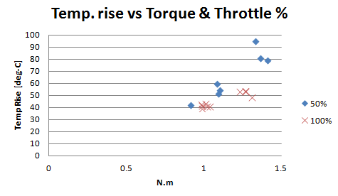
Okay a little bit of data on motor temperature for roughly similar torque but one at 100% throttle, and one with the throttle reduced to slow the motor to roughly half the speed, resulting in significantly less BEMF. The motor under test is an SK3-6364-190kv, the load is provided by regen braking a C8085-250kv. This means the torque is slightly high at 50% speed, but not massively different.
What is massively different is the dTemp = the predicted equilibirum temperature above ambient.
At full 100% we see things stablise out at ~53 deg-C above ambient
But at 50% speed we see the temperature heading for ~80-90 deg-C above ambient. Suggesting 60-80% more heat.
The predicted temperature are based on curve fitting and extrapolating the data, but even before I extrapolated data beyond the ~8mins of data collected, the 50% temps were about 20-degC above the 100% temps. I am not sure I'll read in to any different between the 8kHz and 16kHz temperature data, as they are all extrapolated.
So my explanation is the lower motor speed means lower BEMF. This means we seem bigger current spike during switching. Resulting in more heat due to the high current peaks.
Would have been nice to be able to dial up the torque to be identical for the two different speeds, but unfortunately I can't do that with the loads I have available easily.
Beginning to get a better understanding of why when you bog down a motor it can heat up so much more.
Code:
Voltage	Throttle	PWM	Avg RPM	Avg Torq.	Eq. dTemp
[Volts]	[%]     	kHz	[RPM]	  [N.m]	    [deg-C]
22.2	   100	     16	3913	    1.27	     53.5
22.2   	50	      16	1919	    1.33	     94.9
22.2   	100     	8 	3915	    1.23	     53.6
22.2	   50	      8 	1931	    1.36	     81.0
Summary:
- running the same torque, at a lower RPM significantly increases the waste heat in a motor.
adrian_sm
1 MW
I found it weird too, and still don't trust the results. Here are a few reasons why, or at least things to consider in interpreting the results:
1) Temperature measurements were taken with a IR thermometer pointing past the moving bell end, at the windings. So it is indicitive of the motor temp, but not directly the winding temp. Also about 1deg-C variation in measurements
2) final predicted equilibrium temp is based on extrapolating the temperature readings, and fitting to a exponential rise curve. Dodgy data point can skew this, as with any extrapolation.
3) Torque loads were not identical, due to temperature effects in the load motor and controller
4) Throttle condition is not perfect, I based it on motor speed, not measured PWM widths.
Anyway here is the raw data for the 8 & 16 kHz runs, identical otherwise.
So, assumming the data is correct..... iron hysteresis losses ????
adrian_sm
1 MW
A few data points of the predicted equilibrium temp for various conditions.
Observations:
1) higher torque means higher temp
2) partial throttle same torque means higher temp
and from before
3) 16kHz WM has higher temp than 8kHz for partial throttle condition, but not at full throttle

Observations:
1) higher torque means higher temp
2) partial throttle same torque means higher temp
and from before
3) 16kHz WM has higher temp than 8kHz for partial throttle condition, but not at full throttle
Code:
Voltage	Throttle	PWM	Avg RPM	Avg Torq.	Ambient	Fin. T	dTemp1	Eq. dTemp	Source	Controller
[Volts]	[%]	kHz	[RPM]	[N.m]		[deg-C]		[deg-C]
22.2	50	?	1130	1.1	23.2	69	45.8	55	SK3 6364-190kv (10)	CON61
22.2	50	16	1919	1.33				95	SK3 6364-190kv (11)	YEP 150
22.2	50	8	1931	1.36	22.6	98	75.4	81	SK3 6364-190kv (9)	YEP 150
22.2	50	8	1966	1.41	22.6	92	69.4	79	SK3 6364-190kv (8)	CC ICE 100
22.2	50	?	2047	1.09	22	70	48	52	SK3 6364-190kv (7)	dLux100
22.2	50	?	2082	1.08	22	80	58	60	SK3 6364-190kv (5)	Turnigy Sentilon 100A
22.2	50	?	2140	0.91	22	60	38	42	SK3 6364-190kv (6)	EB306
22.2	75	8	3047		25	63	38	44	SK3 6364-190kv	Tz85A
22.2	100	8	3817	1.01	23	65	42	44	SK3 6364-190kv	Tz85A
22.2	100	8	3883	1.31	24	69	45	49	SK3 6364-190kv	Tz85A
22.2	100	16	3913	1.27				54	SK3 6364-190kv (11)	YEP 150
22.2	100	8	3915	1.23	22.6	75	52.4	54	SK3 6364-190kv (9)	YEP 150
22.2	100	8	3978	1.27	22.6	75	52.4	54	SK3 6364-190kv (8)	CC ICE 100
22.2	100	?	4020	1.04	24	63	39	41	SK3 6364-190kv (4)	SuperBrain 100A
22.2	100	16	4020	1.02	24	64	40	41	SK3 6364-190kv (2)	Tz85A
22.2	100	8	4020	0.99	24	64	40	42	SK3 6364-190kv	Tz85A
22.2	100	?	4027	0.99	20	59	39	40	SK3 6364-190kv (7)	dLux100
22.2	100	?	4266	0.985	22	64	42	43	SK3 6364-190kv (5)	Turnigy Sentilon 100A
22.2 50 16 24 -24 SK3 6364-190kv (2) Tz85AHi Adrian,
Hats off to you for one of the most informative threads on ES recently! Excellent job.
The expectation (e.g. as quoted above) that higher PWM frequency should give smoother current and therefore smaller losses is clearly contradicted by Adrian's data in previous posts.
Fechter's sig says (something like) "one experiment is better than 1000 opinions". So here (diagram copied below) we have experimental data suggesting it is a very poor idea to run an RC motor and controller at 50% PWM. Yet in other applications (e.g. from a toyota prius to commercial wind power generators) engineers manage to make systems that are efficient over a very wide PWM operating range. Could it be that it is a bad idea to feed the motor the high PWM frequency at all? A controller could be made to include a voltage step up/down stage using a high frequency optimized inductor/transformer separate from the commutation modulation. I put together a controller like that a long time ago, but never managed to make it run reliably. (It would blow $500 of FET's and vaporize the circuit board ever so often...)
http://endless-sphere.com/forums/viewtopic.php?f=7&t=19993&hilit=kamyr&start=15#p292906
Adrian: do you have power data to calculate the motor efficiency? It would be nice to get a sense of the efficency hot one takes for running a motor at less than full throttle. My guess would be that for the 1.4-ich nm load condition the 50% PWM 80C case might correspond to double the motor waste heat over the 100% PWM 50C case.
Ideal would be to measure actual power to motor, but it might be ok to measure input power to controller and subtract controller power loss (0.7V*phase amps*0.5 for a regular controller?? or close to 0 for an active rectification controller ??). With some power values it would be interesting to study the relative magnitude of input power, power loss in controller, power loss in motor and output power for different modulations.
(Once term is over I was planning to make an electric drive for my kayak. This is for a simple Minnkota endura trolling motor. I was debating between using a simple PWM brushed controller or a (set of) efficient DC-DC converters for voltage regulation from 48V battery to 4-15V variable out to trolling motor. Guess I should go for the later...)
Martin
Hats off to you for one of the most informative threads on ES recently! Excellent job.
adrian_sm said:Miles said:"Expected", for me, because I've seen other references to it. I've never seen a detailed analysis, though. I've just assumed that, if the motor inductance or the PWM frequency aren't high enough, the motor losses increase significantly with the duty cycle. If anybody knows more about this, I'm all ears....adrian_sm said:Can you explain why?
Miles said:Curious..... I would have expected there to be a reduction in losses at the higher PWM frequency...?
I guess this is the reason that slower wound hub motors seem to be better for hill climbing.....
The expectation (e.g. as quoted above) that higher PWM frequency should give smoother current and therefore smaller losses is clearly contradicted by Adrian's data in previous posts.
Fechter's sig says (something like) "one experiment is better than 1000 opinions". So here (diagram copied below) we have experimental data suggesting it is a very poor idea to run an RC motor and controller at 50% PWM. Yet in other applications (e.g. from a toyota prius to commercial wind power generators) engineers manage to make systems that are efficient over a very wide PWM operating range. Could it be that it is a bad idea to feed the motor the high PWM frequency at all? A controller could be made to include a voltage step up/down stage using a high frequency optimized inductor/transformer separate from the commutation modulation. I put together a controller like that a long time ago, but never managed to make it run reliably. (It would blow $500 of FET's and vaporize the circuit board ever so often...)
http://endless-sphere.com/forums/viewtopic.php?f=7&t=19993&hilit=kamyr&start=15#p292906
Adrian: do you have power data to calculate the motor efficiency? It would be nice to get a sense of the efficency hot one takes for running a motor at less than full throttle. My guess would be that for the 1.4-ich nm load condition the 50% PWM 80C case might correspond to double the motor waste heat over the 100% PWM 50C case.
Ideal would be to measure actual power to motor, but it might be ok to measure input power to controller and subtract controller power loss (0.7V*phase amps*0.5 for a regular controller?? or close to 0 for an active rectification controller ??). With some power values it would be interesting to study the relative magnitude of input power, power loss in controller, power loss in motor and output power for different modulations.
(Once term is over I was planning to make an electric drive for my kayak. This is for a simple Minnkota endura trolling motor. I was debating between using a simple PWM brushed controller or a (set of) efficient DC-DC converters for voltage regulation from 48V battery to 4-15V variable out to trolling motor. Guess I should go for the later...)
Martin
adrian_sm said:A few data points of the predicted equilibrium temp for various conditions.
Observations:
1) higher torque means higher temp
2) partial throttle same torque means higher temp
and from before
3) 16kHz WM has higher temp than 8kHz for partial throttle condition, but not at full throttle
Adrian & Martin,
We definitely need to do more experimentation before we come to any conclusions on this.....
For sure, my expectations were based solely on what I've read... eg:
We need some data for sine commutation at low duty cycle, too... I think that's where the efficiency gains are to be had.
We definitely need to do more experimentation before we come to any conclusions on this.....
For sure, my expectations were based solely on what I've read... eg:
From the Microchip NotesTwo things to consider
with PWM are, the MOSFET losses due to switching,
and the effect that the PWM rate has on the motor.
Higher PWM frequencies mean higher switching
losses, but too low of a PWM frequency will mean that
the current to the motor will be a series of high current
pulses instead of the desired average of the voltage
waveform. Averaging is easier to attain at lower frequencies
if the parasitic motor inductance is relatively
high, but high inductance is an undesirable motor characteristic.
The ideal frequency is dependent on the
characteristics of your motor and power switches.
We need some data for sine commutation at low duty cycle, too... I think that's where the efficiency gains are to be had.
adrian_sm
1 MW
jag said:Adrian: do you have power data to calculate the motor efficiency? It would be nice to get a sense of the efficency hot one takes for running a motor at less than full throttle. My guess would be that for the 1.4-ich nm load condition the 50% PWM 80C case might correspond to double the motor waste heat over the 100% PWM 50C case.
Ideal would be to measure actual power to motor, but it might be ok to measure input power to controller and subtract controller power loss (0.7V*phase amps*0.5 for a regular controller?? or close to 0 for an active rectification controller ??). With some power values it would be interesting to study the relative magnitude of input power, power loss in controller, power loss in motor and output power for different modulations.
Yeah have heaps of efficiency data, as I measured input volts & amps, output torque and speed. So that gives the overall system efficiency. Which was typically up around 86-88% at full throttle, dropping to 77-80% at 50% throttle/speed.
But the temperature measurements for each component (ESC or motor) is the best indication of the waste heat, which is what I am most concerned about. I also measured the cooling temp decay curves, so if you get fancy and measure thermal masses etc, you can theoretically equate this all back to power. I just want to know the operating limits for each of the components. It used to be the controller being the weakest link, but now that I have found a good cheap controller with synchronous rectification, the motor at partial throttle seems to be the weakest.
As for equate the temp rise to th waste heat. It should be a 1:1 relationship. Twice the temp rise should be twice the waste heat.
adrian_sm
1 MW
Miles said:Adrian & Martin,
We definitely need to do more experimentation before we come to any conclusions on this.....
For sure, my expectations were based solely on what I've read... eg:
From the Microchip NotesTwo things to consider
with PWM are, the MOSFET losses due to switching,
and the effect that the PWM rate has on the motor.
Higher PWM frequencies mean higher switching
losses, but too low of a PWM frequency will mean that
the current to the motor will be a series of high current
pulses instead of the desired average of the voltage
waveform. Averaging is easier to attain at lower frequencies
if the parasitic motor inductance is relatively
high, but high inductance is an undesirable motor characteristic.
The ideal frequency is dependent on the
characteristics of your motor and power switches.
Here is a relevant post from a while back with typical inductance and voltage for this type of setup.
http://www.endless-sphere.com/forums/viewtopic.php?f=30&t=29852&p=439576&hilit=adrian#p439576
Now I am assuming that the relevant voltage is battery - BEMF, then the time period depends on the PWM frequency, then the current spikes are determined by the inductance.
So at half speed/throttle we would be seeing current ripples of ~20Amps at 16kHz, and ~40Amps at 8kHz.
Now the data showed that we had more heat at the higher PWM frequency. So my money is on the hysteresis losses in the steel, swinging the magnetic field back and forward twice as often.
If that is the case, the losses will be proportional to the strength of the magnetic field, and the switching frequency on the control side of the equation. And dominated my lamination thickness on the construction side of the equation. Meaning to reduce heat I would need to reduce the load (opposite of what I want to do), lower the switching frequency (limited here), or get a better motor with thinner laminations or something .....
Time to test a few different motors I think.
I'll run a few more test at 50% throttle from cold to get more data points and ensure the observations aren't dodgy. Then I will try a few different motors I have on hand and see what happens.
What other tests/data would people like to see to explore this little conundrum?
We need some data for sine commutation at low duty cycle, too... I think that's where the efficiency gains are to be had.
There aren't a lot of commercially available sensor-less sine commutation controllers unfortunately. I might be able to get my hands on one of the LSDZS ones for a brief period, but I want to make sure I make the most of the testing before I grab it. So I need to make sure I now how to test it, and what to look for. Which comes back to understanding what mechanism is creating the huge increase in waste heat.
- Adrian
Hysteresis losses are proportional to the commutation frequency, not the PWM frequency. I certainly wouldn't expect them to increase with PWM, if anything the opposite.... Eddy current losses in the magnets should also reduce with higher PWM frequency...adrian_sm said:Now the data showed that we had more heat at the higher PWM frequency. So my money is on the hysteresis losses in the steel, swinging the magnetic field back and forward twice as often.
If that is the case, the losses will be proportional to the strength of the magnetic field, and the switching frequency on the control side of the equation. And dominated my lamination thickness on the construction side of the equation. Meaning to reduce heat I would need to reduce the load (opposite of what I want to do), lower the switching frequency (limited here), or get a better motor with thinner laminations or something .....
adrian_sm
1 MW
So where does that leave us?
What correlates with more motor heat at higher PWM?
Definitely repeating the tests from cold tomorrow.
What correlates with more motor heat at higher PWM?
Definitely repeating the tests from cold tomorrow.
adrian_sm said:Summary:
- running the same torque, at a lower RPM significantly increases the waste heat in a motor.
The SK3 63xx have a built in fan (see here), so at lower RPM you will have less cooling...
adrian_sm said:I measured input volts & amps, output torque and speed. So that gives the overall system efficiency. Which was typically up around 86-88% at full throttle, dropping to 77-80% at 50% throttle/speed.
Miles said:Hysteresis losses are proportional to the commutation frequency, not the PWM frequency. I certainly wouldn't expect them to increase with PWM, if anything the opposite.... Eddy current losses in the magnets should also reduce with higher PWM frequency...adrian_sm said:Now the data showed that we had more heat at the higher PWM frequency. So my money is on the hysteresis losses in the steel, swinging the magnetic field back and forward twice as often.
I'm certainly no expert in the design and analysis of electromagnetic machinery. However it seems to me that significant hysteresis and eddy current losses are caused whenever there is rapid change in magnetic field strength, independent of if commutation or PWM is the source. Commutation causes large magnitude changes, but of a moderate frequency. PWM causes small magnitude changes, but with much higher frequency. (Some scope shots i saw on ES years ago suggests current ripple is maybe 10% of mean current, but that may have been a hub motor.)
In a simplified linear model we could view it as two decoupled sources of loss. Then commutation losses would increase with commutation frequency/rpm, but PWM losses are (perhaps surprisingly) independent of PWM frequency. As PWM frequency increases current ripple goes down, but the proportional loss due to hysteresis increases. In a linear operating region these can balance so that
current ripple ~ 1/PWMfreq
hysteresis loss ~ PWMfreq
and the product of the two is constant.
Adrian saw increased loss at 16kHz compared to 8kHz, so a linear model does not seem quite sufficient, though maybe it could give a rough explanation to why motor efficiency dropped from 86-88% at 100% throttle/PWM and no PWM to 7-80% at 50% PWM duty cycle for otherwise pretty similar motor torques.
Adrian: you did the 50% PWM by lowering motor RPM.adrian_sm said:What other tests/data would people like to see to explore this little conundrum?
How about keeping motor rpm constant (and therefore motor operation characteristics constant) Instead use different controller voltages to get several different PWM duty cycles?
For example, with a controller capable of 2-6s LiPo
with 2s run at 100% PWM, measure rpm, torque and electricals.
with 4s adjust pwm to same rpm and torque (should be approximately 50%), and measure.
with 6s adjust pwm again (should be approximately 33%) and measure.
Martin
adrian_sm
1 MW
walls99 said:adrian_sm said:Summary:
- running the same torque, at a lower RPM significantly increases the waste heat in a motor.
The SK3 63xx have a built in fan (see here), so at lower RPM you will have less cooling...
The fan is a joke. No perceptible air flow, so I doubt it has any measurable affect at the RPM I have been running.
EDIT: And opening your link it looks like you come to a similar conclusion given your additional external fan.
adrian_sm
1 MW
That is similar to my hunch. It is the higher frequency current ripple that is causing heating of something, most likely hysterisis losses in the iron. This matches with the test data.jag said:I'm certainly no expert in the design and analysis of electromagnetic machinery. However it seems to me that significant hysteresis and eddy current losses are caused whenever there is rapid change in magnetic field strength, independent of if commutation or PWM is the source. Commutation causes large magnitude changes, but of a moderate frequency. PWM causes small magnitude changes, but with much higher frequency. (Some scope shots i saw on ES years ago suggests current ripple is maybe 10% of mean current, but that may have been a hub motor.)
.
.
Then commutation losses would increase with commutation frequency/rpm, but PWM losses are (perhaps surprisingly) independent of PWM frequency. As PWM frequency increases current ripple goes down, but the proportional loss due to hysteresis increases.
Just to clarify the efficiency figures I quotes were system efficiency, not motor. So includes ESC losses etc.jag said:Adrian saw increased loss at 16kHz compared to 8kHz, so a linear model does not seem quite sufficient, though maybe it could give a rough explanation to why motor efficiency dropped from 86-88% at 100% throttle/PWM and no PWM to 7-80% at 50% PWM duty cycle for otherwise pretty similar motor torques.
jag said:How about keeping motor rpm constant (and therefore motor operation characteristics constant) Instead use different controller voltages to get several different PWM duty cycles?
Yeah I can do those tests easy enough, within the range of my power supply adjustment, but I am not sure it will enlighten me. With a lower voltage we will have a higher PWM %, and lower current ripple ( from lower V-BEMF), so it will all run cooler. I'll get some figures say it runs say ~10 deg-C cooler for he same torque, same RPM, but lower voltage.... It doesn't help me apart from reinforcing the obvious of not gearing your drive train too high.
I found the built in fan air flow wasn't negligible at ~4000RPM but not sufficient for me as I run the motor at 160A and needed more air to help with the ~500W of copper loss.adrian_sm said:The fan is a joke. No perceptible air flow, so I doubt it has any measurable affect at the RPM I have been running.
EDIT: And opening your link it looks like you come to a similar conclusion given your additional external fan.
adrian_sm
1 MW
Hmmm, thanks for that. I was just using my hand to try and detect it. I obviously need to either get my hand recalibrated or take up smoking so I can actually see what the airflow is doing. :lol:
adrian_sm
1 MW
Oh and I have a cheap DSO Nano v2 1Mhz scope so if anyone wants some crappy quality views of phase voltages to help solve the riddle, let me know.

Similar threads

- Replies
- 15
- Views
- 5,173
- Replies
- 1
- Views
- 393
- Replies
- 35
- Views
- 8,105