mon-goose to MON-STER

battery box was suposed to be ready today (chanels and end plates) but got pushed back to tomorow.
i rang a cnc milling place that does small jobs and they want $100 per hr, im in the wrong business! anyway, i think ill make a jig and use my dremel and drill..
thick green lines represent vents, obviously i would do them all the way around , but leave solid areas near screws.
vents in side plate.JPG
 
pendragon8000 said:
So NeilP, you got ideas about amp limit and phase limit?

What ever Lyen recommends to start with and go from there.
4115's are less current than 4110's so ?? I can't rmember what Lyen said now. Check the sale thread and your e-mails with him..or ask him.
Seem to think 60 to 90 Max battery, VERY MAX.
Phase..well the uysual 2.5 to 3 times that

Voltage well the FETS are I believe good for 150 volt MAX, so keepign donw to 132 is recommended. but they can be pushed, but you do risk blowing them with spikes etc.

With high current setup figures..keep the block time low XPD allows setting 0.1 or even 0 seconds
 
Thanks for the help Neil. Ill see how Lyen set it up soon and go from there.
Ill have to read up on how phase curent and main current limits change behaviour of acceleration etc.
lucky i have an eepc net book i can put in my back pack and change things and test and try and change.
 
I would be careful with making your side cover look like Swiss cheese. Keep in the back or your mind that your transfer the torque through the covers. And since your running the HT motor with that much power, why don't you see how your motor cools with these holes? or limit your self to just one of this other holes?
I don't want you to finally build your bike up just to see cracked side covers and shelf it for a week or two to wait for some more. If your going to make a video, I want it to be atleast 5 minutes not 7.5 seconds :wink:
 
LOL HAHA, yeah.. sory i should have said that a pic from my first bike.. thats the motor from the hadron kit from hyena. i wont drill massive holes in it AND do vents , the idea with the vents is more turbine efect from more edges and more venturi effect from, well... more edges. also as you say the torque travels through the plate, but from the screws to the bearing so, i gota keep metal around the screws and thats why ill do groups of vents between screws. i dont think personally that it would make that much difference if one side is drilled and the other not, but i would assume that it would be a more efficient use of metal mass to share the holes on both sides. and also ill go with "air in" holes near the axle.. just a few 10mm i think.
anythoughts on lots of smaller holes as oposed to a few bigens?
 
you'd better read this thread if not done :
http://endless-sphere.com/forums/viewtopic.php?f=2&t=9791&start=585

I got plans, that I haven't seen outathere...if my understanding of the english, reading 1/2 lines...we try to have a better air dissipation/circulation near the magnets/wiring...
PLAN A
If I can curve (with a press ...) 2 or 3 radiators to the external radius of the Hub, applying thermal grease and soldering (fixing @least)...(this is alloy :wink: and probably not Cromo one as frames...), it won't ad so that much drag, nore inertia, but more dissipation surface...
$(KGrHqR,!kwE+5)HdV(cBQBRtc3oOw~~60_3.JPG

PLAN B using holes, for circulation I think baldes inside the hub is the best , but we have to work with the best splines design and experiment if the drag does'nt input more power...not to eat more power due to the drag...heating more power to fresh it...the snake biting its tail...
PLAN Y : use the ...what is the name of the magic red paint ?still recommanded ?
PLAN C push more vent inside :
cheap experiment 12V , with a pipe for feeding the top front quater of the hub, considering the flow throw the quater rear @ ground
$(KGrHqF,!hMFBcIHE9!rBQgDz)J3-!~~60_57.JPG

or even with a compressor which can be usefull for inflate, or just if you're stocked waiting for the hub to cool down...
$(KGrHqV,!pcF!H57VsEyBQUZl-h51Q~~60_12.JPG


I would experiment blowing air with 1 or 2 pipes coming for the front with 1 or 2 scoops + a PC airfans+ filter (and a switch for freewheel use with for low speeds) to just push the air on the side of the hub cause it is pretty turbulent around the wheel...
@least again it would help freshing if in need of a stop and could cool the controller if in need too
!B-p-72wB2k~$(KGrHqIOKj4EzYUZ8HpIBM9UM2s2bg~~_12.JPG

4b_1.JPG

and the best scoop for the end :D
$(KGrHqMOKiUE14p)qYv,BNn80YChYw~~_12.JPG

scoops with eyeshots :wink: :wink: :wink:
 
dan974 said:
you'd better read this thread if not done :
http://endless-sphere.com/forums/viewtopic.php?f=2&t=9791&start=585

I got plans, that I haven't seen outathere...if my understanding of the english, reading 1/2 lines...we try to have a better air dissipation/circulation near the magnets/wiring...
PLAN A
If I can curve (with a press ...) 2 or 3 radiators to the external radius of the Hub, applying thermal grease and soldering (fixing @least)...(this is alloy :wink: and probably not Cromo one as frames...), it won't ad so that much drag, nore inertia, but more dissipation surface...
$(KGrHqR,!kwE+5)HdV(cBQBRtc3oOw~~60_3.JPG
having an ambient temperature shell and hot coils relys on the air inside transfering the heat and im prety sure that is a slow process. if it were oil filled that would be a different story.
having air flow across the coils is the goal for me. i looked at oil cooling but its alott of work and i will have my hands full getting this all done as it is so, i'll stick to air cooling, i think it's worth a try to improve on the 20mm x 9 holes NEAR the coils/windings. I want to get the vents close to the edge of the side plate so air is being sucked over the edge of the coils, not just from underieth (cant explain 3d thoughts! h :x ) anyway.. the only thing i havent decided on is if i should have them angled or straight out. angled would be better for air turbine / centrifugal, and straight seems like it would be stronger and better for venturi effect at the top of the hub where air is moving across the vents the fastest.
thanks for the link ill have a read.
and nice scoop :)
 
30watt LED light
2 rows of 5 3watt cool white leds
View attachment 1
i have 5 x 10º,5 x 22º and 5 x 45º reflectors
30watt front light2.JPG
i think ill have 1 row for wide beam (45º with no reflectors on the side ones) and 1 row for spot(10º with a 22º on each side) with a switch on the spot so its not too hard core for other riders on bike tracks. funny how its ok on the road though, i guess ppl arent as close coming the other way...
30watts should be nice and bright though :) for those that dont know a single 1 of these leds would be about the same as a normal ($25-$40) bright bike light, and i got 10.
 
pendragon8000 said:
Blew 2 leads, I think the info in the eBay page is incorrect. Didn't go to high with voltage...or there qc is shit and the tollerane percentage is too high. Anyway reconfigure to 4x2 still 24watts. I'll have to under volt to keep them from blowing.

Are you connecting the lights directly to the battery? If I were you, I would get a dc-dc converter on that.
It's all about the learning process. The more mistakes you make now, the less you will make later :wink: . Just about everybody here can attest to that lol
 
Sory I said leads but it was LEDS . 2 died. I am using a DC converter. Its got a switch to choose 9v -20v I had it on 18 I think but 15 is enough to make them shine at full brightness (3v each) the leds are rated for up to 4.2v so theoretically 20v should be ok for a string of 5.
 
LIGHT1.JPG
LIGHT2.JPG
Light 8) bloody bright! old CPU heatsink and fan, turned fan around so it goes with venturi efect of air blowing over sides of heatsink, doesnt get warm at all so might ditch fan cos its a bit noisy, i really love quiet riding with the DD hub :)
so yeah thats done although will smash acrylic if/when i have a stack.. ill see how it holds up..
oh yeah, got 10º on the narow beam and 45º on the wide with the side ones sides dremeled to let a bit of light out the side, wouldn't be much with refraction keeping the light in the acrylic parbolic reflector.
and here is my battery box, i took it back and they were happy to fix the lid, nice family owned and run business :)
 
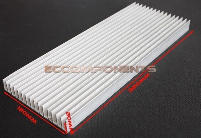
just opened the Lyen 18x4115 fet controller and had a sus.. it looks prety good, already has beefed up tracks (neg, pos, and 3 phase) looks like a solid piece of copper wire was layed over and a TON over solder melted on there so i think if i added any more it would be excesive. I did add some Unick thermal paste to the fet block that presses against the heatsink shell/box/case cos it was very minimal. I will probably add a thermostat with buzzer so i know if its getting stressed. most controllers dont seem to get too hot b4 the motor does. so ill probly use about 70ºC alarm temp. the delay in heat to the thermostat from the components(fets) getting hot needs to be compensated for by having a lower temp switch IMO. its no use having the buzzer go off when it gets to 100ºC when the fets are 150ºC . so there may be a few false alarms when doing long hills but at least i wont kill it or if i do it will be my own fault.

anyway, i'm still waiting for the batteries and the battery box lid to be redone. i have to order a few conectors and a couple battery monitors, the 2 spare i have are unavailable from HK atm so ill get 2 others that do the same, would like to be all the same, but haveing 2 diferent monitors could be of some use if 1 starts to play up.

so what i still have to do..
- Open the hub and thermostat the halls, t9 spray the stator, vent the side plates. (to do this i need a gear puller but dont know where to get a big enough one so might conect it to screws on the disk mount and mdf or something screwed onto gear side freewheel thread.)
-Rear light, should be easy. 5 x3w leds epoxyed to aluminium plate.
-program controller, not sure if i should try it first with Lyens specs or just go for it and try my own.
-start welding the frame, have to cut off old steer tube housing and weld on new one, cut frame down tube and weld in battery box.
-make a second torque arm, might just make it a small one that uses the bolt hole on the drop out.
- order new bar,head stem,wheel,203mmdisk brake and a few other bits from CRC
-Get some epoxy spray paint.
-CA V3 and 7 speed 11-32 from ebike.ca
Its a bit anoying not having all the parts here at once. I dont need them all but I'm hesitant to really get stuck into it without being able to mesure diferent parts that have to fit together etc, make sure its all compatible.
I should bite the bullet and do the battery box and open the motor. after that i can see how the controller sits under the batteries or on the top tube.
I'm hesitant to cut off the steer tube housing b4 i get new head stem and handle bar.
---- just checked my shoping list on crc, the wheel i was waiting for is now available so i ordered up on everything i need.
DMR factory front wheel
22972.jpg
 
diy gear puller.JPG
its a bit gettho..
but it should work.
so ill undo the screws in the bottom side and wind the axle and guts through the rotor/shell. then its game on to vent side plates and thermostat halls. and install 10k ntc thermistor.
got a nice little drill press from jaycar today, $30.
productLarge2_16388.jpg

so ill drill all the holes with a jig that alows the plate to rotate on the centre axle hole and clamp it when i drill each hole, then have the rotating jig on a slideing draw thing that moves a few cm, ill put a couple screws as stoppers so i can just rotate it clamp it lower milling bit in hole and slide it to the stop and repeate. ill do the first of each bunch between screws so if the bit gets worn half way through i can finish that set and have a blanaced wheel rather than having one side vented with milled out fins and the other side just holes.. also got spray on enamel for the motor windings/coils, i was looking for urethane but could find any, enamel is pretty good though. a few coats of that should be fine.
 
Why are you getting another rim? I thought crystalyte made some good sturdy rims :? You might want to save your money and stick with it.
 
pendragon8000 said:
Trackman, are you referring to the dmr I ordered from crc?Thats a complete _front_ wheel. The spoke holes are too big IMO on the crystalyte rim, but yeah it seems like a keeper.
Yes I am/was!
Sorry, when I'm browsing this site on my phone, I have a tendency to half read a post and think I know what I am talking about :shock: ..... bad habbit, its gotta stop lol
Really like how everything is working out for you. What is the eta for the batteries?
 
I actually ordered 3 from international wh 'cos I neded 2 for other bike and made up package weight. And 7 from Australia.Got the 7 on Friday. Probly get the 3 on Monday tomorrow.
I'll show the milling process shortly... shit just remembered I was supposed to get a new 3.5mm drill bit at bunnings, just got back from there. Hopefully the old one I have can get through the 72 holes...
Got a make the slide from mdf now. Ivemarked up 1 side plate to start drilling and milling.
 
Back
Top