Homemade Battery Packs

spuzzete said:
@ DrkAngel

Thank you for your explanation, it makes perfect sense. :)

@Etriker

The datasheet says 3.6v nominal and 4.2v fully charged. I believe that the final voltage after recharge has influence on the discharging curve too.

And everything else too ? Temp, age, cycles, discharge current.

Also what is inside the cells. Different brands are different inside and do not discharge the same.

I don't ever run the bike until cells go lvc or off the cliff. That is why we have pedals ? :)

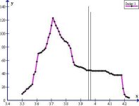
After the pack is built I test it and see where the cells go off the cliff, in parallel, in the built pack and rate the pack.

If it is a 12 ah pack I don't use more than 10 ah at the most before recharging.

Heck, if you built it you can call a 12ah pack a 10ah pack and only use 8ah before recharging if you want ? :)

You are the bms ? :)
 
Bleed Down - Voltage "Leakage" Test

Object - To apply a preliminary charge to a quantity of cells as 1st step in determining condition and usability.

Procedure -

Step 1
Confirm all cells at some voltage ... 3-3.5V?
Gang all cells together.
(Since there is a minimal amount of energy present, at this low voltage, rate of transfer between cells is moderate. )

Step 2
Apply 4.2V charge to cells (These particular type cells have been predetermined to retain good capacity at 4.20V.)
Monitor for any cell producing heat, if found , cut out of circuit.

Step 3
Separate all cells after 4.2V retained.
Check cells individually at 24 hour intervals, removing any with voltage bleed down.
(All cells "bleed down" some, remove those with "excessive" voltage loss.)

Tools

MeanWell modded for 4.2V and lower (Outputs ~35Amps at 4.2V)
IR temp meter - saves singed fingers.
Soldering iron etc.
 

Attachments

  • 40p.jpg
    40p.jpg
    86 KB · Views: 8,832
  • Bulk Charge.jpg
    Bulk Charge.jpg
    68.4 KB · Views: 8,832


I wanted to share my recent interchangeable battery build. It is about as homemade as homemade batteries get with me (no CNC machine involved).

All of the nickel terminating was done at a batteries plus. They were kind enough to let me use their welder one morning. Since then, however, I have been using my own homemade welder to make over 4000 90 watt-second welds on my A123, 336 cell motorcycle pack.

[youtube]Wxe7ccUJGB8[/youtube]

First thing I did was figure out what form factor I wanted 20S5P a123 to be in. Then I modeled the pack in CATIA (CAD) and drew out a template for a battery bag. I left about 2-3mm on all sides. Then I printed out the template to scale, taped all the pages together, cut out then outline, then transferred it onto some .024" nylon I got from McMaster for less than $25 (for 4 bags). Then I took a straight edge and drew lines where all the seams would be so I would get an even bag after hand stitching.

Then I sat down and watched history channel. It took about 3 hours per bag to hand stitch.

I put a piece of bent .125" polycarbonate underneath the battery to protect the back corner that contacts the seat tube (to distribute the load). Also, I first taped each halve of pack according to picture. Then I taped the two together. THe tape compressed between the two halves acts as a bit of a shock absorber.

Note: I designed it so all the weight was not on too many stitches. The only weight on stitches is that holding Velcro onto fabric.
 

Attachments

  • IMG_2994.jpg
    IMG_2994.jpg
    54.3 KB · Views: 8,952
  • IMG_2993.jpg
    IMG_2993.jpg
    57.4 KB · Views: 8,952
  • IMG_2972.jpg
    IMG_2972.jpg
    39.2 KB · Views: 8,952
  • IMG_2974.jpg
    IMG_2974.jpg
    67.5 KB · Views: 8,952
  • IMG_2977.jpg
    IMG_2977.jpg
    42.6 KB · Views: 8,952
  • IMG_2980.jpg
    IMG_2980.jpg
    48.8 KB · Views: 8,952
  • IMG_2992.jpg
    IMG_2992.jpg
    74.2 KB · Views: 8,952
Hello guys,
First i wanted to thank you all for this great thread. It's great to have such a valuable information here :)
So let's get back to me. I wanted to share and have your opinion about my 18650 battery testing method. I separate every cell and charge them fully, then i check voltage dropdowns. After several days i apply 1a test on each cell for 2min exactly and write down voltage reading. I group batteries with same discharge rate and parallel them (i try not to mix different brand cells). Low grade batteries ussually shows low voltage reading after 2min of discharge stress (3.3v or even lower), so i dispose them. I keep cells which manages to stay 3.7v after such discharge. As i'm building large pack, i won't ever exeed 1a for cell discharge rate at any time on bike. So they wont be stressed so much in the future. I'm planning on building 50ah 10-15s and using bafang BPM 36v 500w motor. Should be good for long trips :)
 
"Bleed down" from full charge is my primary condition indicator as well.
I am presently remanufacturing my 2008 builds ... 350+ cells.
These particular 3.7V 2600mah cells retain good energy density above 4.2V.
So I bulk charged batts as 44p, using 4.25V 35A MeanWell, then separate.
After setting 7 days I am segregating into piles of 4.24V, 4.23V, 4.22V, 4.21V, 4.20 4.20V - 4.15 and then "bin jobs".
4.2V minus will be used in some bulk power inverter pack charged to 4.10V, or lower?
(Finished packs will be charged to only 4.15V, possibly only 4.1V. Increased lifespan should outweigh decreased capacity, the majority of energy density, of these cells, is concentrated in the 3.7V -3.9V range!)

2600mah cells are bonded in 2p so a 1c discharge would be 5200ma.
I will test discharge as 3s2p through 12vdc - 120vac inverters. at a timed (1hr) .5c discharge rate (.3c - .5C my typical usage).
Residual voltage of each pair will be matched as being of equal capacity-condition.
12 cells x 8 hours = 96 cells per day tested.

I will also keep track of the preliminary "residual voltage retained", as an indicator of battery capacity-condition and compare against actual capacity.

My more recent builds are 3.6V cells and laptop LiPo, I restrict charging voltage to 4.10V per cell, that is what the oem chargers-packs supplied, as I expect the manufacturers built for maximum lifespan, with more research than I, I'm inclined to take advantage of their knowledge..
I might even further restrict Lipo charge to 4.05V, as my mah/.001V capacity test showed it as advisable.
 
DrkAngel said:
Sorry ... I never posted my Laptop Lipo recycled pack. (EZip 10ah SLA original case)
84 - 2160mah lipo cells, oem configured in 11.1v "6-packs".
7S12P 3.7v - 7Series 12Parallel
25.9v - 25.92ah pack

file.php


On the side, are 12 separated cells, which make up the 7th bank.
Balance-equalization plug sets flush to side, but extends, when needed.
Black plastic "shelves" were cut from a plastic tub, and were added to support-protect cells.

Clear "boxing" tape used to keep "unruly" wires, "in their place".
Planning my next Lipo build.
For simplicity I intend on a 22.2V build. (24.6V @ 4.1V durability charge voltage)
Similar to picture above, but the 12 side cells will be replaced with 4 3s 2000mah RC Lipo packs, parallel to the recycled Lipo.
This should bump the pack from 26Ah to a full 30Ah.
More importantly ... the surge capability might be doubled!
Balance charging can be accomplished with the budget iMax B6 - about $25.

After initial monitored charges I intend relying on my 10a bulk charger.
(24.6V ... could adjust to 12.5a!
Will continuously monitor all bank voltages and (re-)balance charge as deemed advisable.

Oh ... 2 - 22.2V packs "in series" work nicely on my 44.4 Magnum projects!
 
DrkAngel

I have been reading this thread for a couple days now and my brain is starting to feel like jello. I would like to build a 25.9v li ion battery back as you have. Can you provide a schematic as to the cell configuration and how many cells? are needed? Also you did not use a bms or pcm or anything right? Where did you get the plug to hook to the tenergy charger? How do you "gang" two chargers together? I am sorry I am a total newb. I do not want to pay $400 for a battery back with decent range which is why im going the diy route. I purchased this lot of batteries off of ebay http://www.ebay.com/itm/261157482215?ssPageName=STRK:MEWNX:IT&_trksid=p3984.m1439.l2649 do you think that will be enough cells?
 
25.9V 31.2Ah pack is a 7s(x 3.7V) 12p(x 2.6Ah) configuration. (2600mah cells)
Which is 84 good cells.

attachment.php


I built this size because it fits in the eZip battery pack.
The eZip battery pack uses an XLR, microphone type, power jack. Search on ebay for xlr jack or xlr plug.
Gold plated is preferred!
 
DrkAngel

What was your configuration for the 37v 20ah battery? I think im gonna go 36v it seems at 24v I dont get enough speed/power with my fat ass.
 
dj_justice said:
DrkAngel

What was your configuration for the 37v 20ah battery? I think im gonna go 36v it seems at 24v I dont get enough speed/power with my fat ass.
10s(x 3.7V) 8p(x 2.6Ah) This fits in the oem eZip pack.

file.php

Especially if you are heavy, I would have to recommend a 10s 12p pack, (37V 31.2Ah).
Pretty sure you'll want the extra amps to minimize voltage sag.
Recommend 1C surge and .3 - .5C sustained output!

Oh yeah ... pedal!
Especially getting started, you have much more torque than the motor!
Combined can be impressive!
 
dj_justice said:
Do you think I need a bms with that set up?
A "good" BMS might cost more than the pack ...
A BMS will mask-hide slight problems that would be evident without.
I prefer to spot potential problems, imbalances etc., quickly and easily.

I would recommend carefully monitoring the pack and letting your observations influence that decision.
I do not use a BMS ... but I do carefully monitor!
 
I've been sadly disappointed with any BMS\PCB\PCM that I have tried, $40-$60 range.
"Balance" is typically a trickle bleed-down of the over voltage cells.

I am presently investigating a recent observation.
On a recent purchase of old, setting for years, HP notebook packs, I noticed that all cells in each pack were precisely at the same voltage.
All packs had different voltages, but every cell in each pack was precisely balanced to the 1 hundredth of a volt.
Logical and most likely explanation is that the built in BMS type board was maintaining balance ... without any external power!

Theoretically, overlapping 3 of these across the 7s of my 25.9V builds should maintain, or attain, a voltage balance between all cells.

I would not charge or discharge through these controllers, merely allow them to do their thing ... as they have been for these past many years.
This should simplify bulk charging and make it much safer!

Decided to test by partially draining 1 bank then observing.
 
So would you just charge through the main power connector for the bike? I got an Imax B8 to charge with.
 
dj_justice said:
So would you just charge through the main power connector for the bike? I got an Imax B8 to charge with.
With cells of reasonably stable condition-capacity a bulk charger recharges to the same balance state that it began with.
While using a balance charger continuously would keep peak charge voltages nice and equal, it might tend to mask any new problems, hiding any weakness in one bank. I prefer the occasional monitored balance, but generally rely on bulk charging ... with a monitored DOD and peak charge for each bank. Any noticed problem could be addressed immediately, while relying solely on a balance charger might delay notice till some drastic failure.

I recommend having a balance charger, but generally use a bulk charger.
Monitor voltage of each bank - 1-8S Lipo Battery Low Voltage Tester Buzzer Alarm $2.79

Note on iMax B8 - Very nice item, but had 3 failures, over 4 years, (able to self repair 1 - blown MOSFET). Doesn't like charging my 7s 25.9V beyond 3A output. 2 failures occurred when I tried a full 5A charge rate (+20A 12V input).

3A charge rate on +30A pack took too long ... but.
Dual charge - Trim a bulk charger to slightly below iMax charge-balance voltage ... should apply both charge rates ... bulk charger cutting off early and balance charger applying topping and balance charges!
Rapid charge with balance, best of both worlds!
 
DrkAngel
I am a new member, having just registered so I could write this post.
Thank you, DrkAngel, for starting this topic and contributing so much of your experience. I've been reading this, and most of the other topics for more than a year and finally, this winter, decided to build my own battery. I have now put a couple hundred miles on it and I am extremely pleased with what it has done for my bike's performance and range. The pack is 12p12s 27ah replacing a 36v 12ah lead acid pack. My top speed went from 20mph to 28mph and the range is unbelievable. I got too saddle sore to keep going after 40 miles and the cell logger was still indicating 3.8 volts per cell. Wow, no more range anxiety.
I will try to get some photos posted here next week.
Happy trails,
Art
 
DrkAngel said:
Object - To apply a preliminary charge to a quantity of cells as 1st step in determining condition and usability.

Procedure -

Step 1
Confirm all cells at some voltage ... 3-3.5V?
Gang all cells together.
(Since there is a minimal amount of energy present, at this low voltage, rate of transfer between cells is moderate. )

Step 2
Apply 4.2V charge to cells (These particular type cells have been predetermined to retain good capacity at 4.20V.)
Monitor for any cell producing heat, if found , cut out of circuit.

Step 3
Separate all cells after 4.2V retained.
Check cells individually at 24 hour intervals, removing any with voltage bleed down.
(All cells "bleed down" some, remove those with "excessive" voltage loss.)

Tools

MeanWell modded for 4.2V and lower (Outputs ~35Amps at 4.2V)
IR temp meter - saves singed fingers.
Soldering iron etc.
file.php

file.php

Self-Discharge Test - Step One! Dupe from a thread on BMS, but really belongs here ... too!
Present test on 3.7V - cells were charged to 4.25V, then
allowed to sit, potentially self-discharging for 1 month!(Oops! ... 2 months!)
(These cell were previously determined to hold good capacity at 4.20V+) - see image below
Cells are now being sorted by retained voltage.
4.25V = A++
4.24V = A+
4.23V = A
4.22V = B
4.21V = C
4.20V = C-
Below 4.20V but above 4.15V for separate build.
Below 4.15V but above 4.10V tasked for bulk project ...?
Below 4.10V ... binned or experimentation?

Although testing is for being 4.2V capable, these cells will be charged to 4.15V or less, as a means of prolonging usable lifespan. DOD depth of discharge looks optimal at 3.65V.
Red line is results of capacity - mah/100th V test(5200mAh - paired cells)
Every brand, model, possibly batch, tests differently! I will post easier diagnostic method using 5V Meanwell with Ah meter and 100th V capable meter
Yellow line is results of same test on a specific type recycled Lipo. (4320mAh - paired cells)

file.php
 
Pack Assembly - Step 2
After setting, for about 1 month, I sorted cells by retained voltage.
4.25V preliminary charge.
(These cells were re-re-cycled from my 2008 builds, plus a few "left-overs")

Results
4.23V+ = 52 cells
4.22V = 80 cells
4.21V = 52 cells
4.20V = 44 cells
4.15-4.19V = ~120 cells
4.10 -4.14 = ~20
sub 4.10 = 12 cells
(All cells are tandem.)

I felt it to be pre-ordained that I should build my prototype 22.2V pack using the 96 cells available from the 4.20V and 4.21V piles.
6s 16P x 2600mAh cells = 41.6Ah.
And ... they fit snugly in the oem eZip RMB battery case!(OEM = 24V 10Ah ... 6Ah usable)
Pack was constructed in 2 - 6s 8p modules.
Center screw post could be retained, but I previously removed it.
So I spaced the 2 modules with 1/4" paneling.

Cells were connected using the oem tabs, on the tandemed pairs.
I used 22ga tinned copper braid as balance connection wires.
The "power rails" were built using 10+ga tinned copper braid, ~40-50A capable.
10ga insulated copper wire used to connect the rails to the terminals.
Charging port 22ga wires replaced with 14ga insulated.
(25.9V 10A charger replaced with 22.2V 12A charger - MeanWell Mods)

It should be noted that I performed no capacity test on the implemented cells.
I am testing a theory that retainable voltage is a good indication of condition-capacity.

Also, although I added balance wires, I have not, yet, added a balance plug.
I am planning on using a ethernet plug to attach to ethernet cable to balance charger or VMA (Voltage Monitor Alarm).
Should work nicely with 6s and 7s builds.
Ethernet plug could be safely covered with tape, when not in use?
Ooh! Ethernet covers -
 
22.2V Test Run

22.2V 41.6Ah eZip pack rebuild.
Got the pack together ... packed jamb tight with 96 - 18650 cells.
I even used flattened tinned copper braid to run beside cells.

Ran about 20 miles today.
Tried the pack on 2 different eZips, both with 16T upgrades.
WOT produced an anemic 16-17 mph on the level for the 2009 LS Trailz and 17-18 mph with my 2008 Trailz.
... 19 - 21 mph with 25.9V pack.

Might be fine for:
an oem eZip for casual cruising at 13-14mph ... for 70 - 80 miles?
an eZip with 13T mod with continuous pedaling ... for 20mph sustainable.
or as half of a 44.4V series rig.

file.php


Raining tomorrow, so I will open pack and check all voltages.
After 20 miles, any volt variance between banks should start to be evident.
All cells started at 4.20V and 4.21V.
 
23 mile report - 22.2V 41.6Ah Rebuild pack

23 miles @ ~17mph

25.2V Start - 23.7V after 23 miles

... - 23m
1a = 3.95V
2a = 3.96V
3a = 3.95V
4a = 3.95V
5a = 3.95V
6a = 3.96V
+
+
6b = 3.96V
5b = 3.96V
4b = 3.95V
3b = 3.97V
2b = 3.95V
1b = 3.95V
-
Bank voltage is remaining very close!
Voltages should continue to diverge as pack nears "empty".
Note: - 3b @ 3.97V will be in tandem with 3a @ 3.95V for an actual 3.96V, so actual variance is 1/2 of pictured in graph. So, presently, all banks within 100th V variance. (3.95v-3.96v)Same as starting (4.20v-4.21v)

Present discharge points between lines.
Present discharge about 25-30% ... estimated by area of graph.

file.php


Graph determined using - http://endless-sphere.com/forums/viewtopic.php?f=14&t=33271
 

Attachments

  • 23 Mile Variance.JPG
    23 Mile Variance.JPG
    14.4 KB · Views: 7,815
i got given about 10 of these laptop battery packs today, anyone no any thing about the cells. are there any good for making a battery pack i can't find any info on the net about them.
adam

IMG_03281_zps35d66ac3.jpg


IMG_03291_zpsa721414f.jpg


IMG_03301_zpsf52fdd10.jpg
 
They are LiCo cells made by LG, a reputable manufacturer. Capacity is 2000mAh per cell (you can tell that by looking at the capacity of the pack). They are good typical laptop cells. The question is how much capacity is left in them and the only way to know is charge them up, discharge and measure the capacity.
 
Somebody please comment the following picture and how does this even make sense?

I'm testing one fully charged lap cell for capacity by 0.5A discharge, started at 4.2v

so It has ran for 76mins, at 0.5A now down to 3.6V (gradually from 4.2) and it only got out 637mAh of energy.. at 0.5A? wtf
Even if it would have been 3.6v all the time then I believe that in 1h it should have outputted 1800 mAh ? (3.6x0.5x1) or what am i getting wrong here..

atm it has ran 127mins, at 0.5A, voltage is down to 3.56v and output is 1067mAh ..

charger is imax B6 clone

Photo 18.03.13 12 18.31.jpg
 
Back
Top