Cycle Analyst V3 preview and first beta release

Aux port is Vbatt..umm maybe I did read that somewhere I was thinking it was 12 volt.

maybe I am beign a bit negative today..did nto sleep well last night.. my partners son was staying over..he snores loud...so does she...so I ended up sleeping on the hall floor on a bean bag :( then got called out to work..long shift..5 flights..emergency ones....might see things in a better light in the morning

yep aware of the car nominal 12 volt being higher..13.8. mY car ( Toyota landcruiser '82 ) is actuallt 24 volt..but see 32 on the volt meter

I realised the 10volt was limited ont eh v3 but not the 5 volt too..that really is a massive let down
 
NeilP said:
Or what about 84 volt..(20s LiPo) will it (the v3) run stuff at 5volts at 84 in ?
You have 10ma available at 84v. A hall takes about 5ma and resistive divider 3-position switches, etc for the CA AUX Pot input can be arranged to draw on a couple of ma. Should be in pretty good shape.

NP said:
Maybe there is a way to modify the v3 to give better outputs of the 5 and 10 volt lines at these sort of voltages?
Actually, just helping the CA better address the high Vin to Vout voltage differential may be the answer...

I believe you will be all set if you wire the CA for high voltage operation so it can sense the 134v separately, then power the CA by dropping the 134v with three series 33v 1W zeners ( (134v - 99v) = 35v ). For the zener power rating - figuring 1000mw/33v = 30ma, more than enough for the THUN (20ma) and your throttle (5ma). Any suitable combination of zeners would be okay. At 35v the CA can deliver 50ma of combined 5v and 10v - more than enough for your needs. :D

I don't see why this won't work. Let me fly this by Justin to get his blessing. We are talking about dumping ~2.5W of heat (3 * (33v*25ma) = 2475mw) so I think at worst you might need to mount the zeners outboard back at the controller.

EDIT - If you wanted to get a little fancier, a simple single transistor emitter follower (series) regulator could be used. You could mount the transistor on the controller case to borrow a tiny bit of the heatsink.

Also - Although the above is okay in principle, I forgot to add in 10ma for the CA itself so the power estimate is low and zener selection needs tinkering as well... :oops:
 
Thanks for the ideas.
I can build stuff, even do basic repairs, but understanding how things interact and designing even a simple circuit is always a bit beyond my grasp
A little single transistor reg mounted on board that could be built up so the CA ran in high volt mode for monitoring and was fed from the reg without any extra external DC DC convertors would make it usable at this sort of voltage range

What would one need for the single transistor circuit?
 
NeilP said:
A little single transistor reg mounted on board that could be built up so the CA ran in high volt mode for monitoring and was fed from the reg without any extra external DC DC convertors would make it usable at this sort of voltage range

What would one need for the single transistor circuit?
I still think one of the little netbook switching supplies is better (about 1"x1.5"x3.5") because of the power loss with this linear regulator approach (about 5W in this case). But, this should work fine and can be tacked onto the inside top of your controller - just run the output to the CA-DP connector in place of the present Vbatt. The Vex divider can be tacked onto the CA PCB.

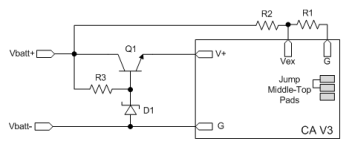
The example below is a minimum-parts emitter-follower using a zener reference. Although the design is very basic and offers poor regulation, the purpose is only to reduce the supply voltage for the CA, allowing the CA regulator to do the actual regulation. The following text indicates how to derive parts values based on the specific battery voltage and suite of CA accessories - this may be useful to adapt this for other available components or situations - if you change the voltage or the accessories, just chug through this again with the new values. I don't have these parts on the shelf and so haven't tried it, but there's not much to it.

CAV3_HvCurrentBoost.png
View attachment TIP47.pdfView attachment 1n4728a-104110.pdf

[pre]1. Determine Icamax = current for CA and all 5v and 10v accessories
typical values:
Ica = 10ma (basic CA PCB operating requirement)
Ihall = 5ma (single hall device)
Ithrottle = 5ma (hall throttle)
Imagura = 1ma (Magura throttle)
Ithun = 20ma (THUN BB)
Ipasreed = 1ma (reed switch PAS wheel)
Ipas2hall = 10ma (2 hall PAS wheel)
Ipresetsw = 0.5ma (typical preset sw)
I3possw = 3ma (typical 3-position switch with divider)
Iauxpot = 1ma (typical PAS or Speed pot = 5K)

If accessories = Thun, hall throttle, and an external 'preset' select switch
Icamax = Ica + Ithrottle + Ithun + Ipresetsw = 10+5+20+0.5 = 35.5ma

2. Determine max voltage (Vcamax) at which CA can supply Icamax
Vcamax = (10*Icamax + 1600)/(Icamax + 10) = (10*35.5+1600)/(35.5+10) = 42.9v

3. Select zener D1 to provide Vcamax + base-emmitter drop (0.8v)
Vselect <= 42.9 + 0.8 = 43.7v
Select zener from datasheet: use exact V or lower
either 39v or 43v zener will do - choose lower to off-load heat from CA to Q1
select D1 = 1N4754A
note Vz = 39v
note Izt1 = 6.5ma = minimum current to maintain zener voltage
note Izm = 23ma = max current

4. Calculate actual CA current capacity at Vz with selected part
Icamaxactual = (1500/(Vz - 0.8v - 10v)) = 1500/(39 -0.8 -10) ~= 53ma
subtracting Ica gives 43ma max for accessories

5. Q1 = TIP47 NPN Vce=250v, Vcb=300v
From datasheet note Q1 DC gain = hfe = 30
calculate base current to supply Icamax
Ib = Icamax/hfe = 35.5/30 = 1.18ma

6. Determine max current through zener (if CA disconnected)
Izmax = Ib + Izt1 = 1.18ma + 6.5ma = 7.68ma

7. Determine R3 to provide required Izmax at lowest pack voltage
for LiPO: Zlo:hi = LVC/HVC = 3.38v/4.17v = 0.81
derate to keep CA running at 85% LVC:
Zlo:hi' = Zlo:hi * 0.85 = 0.81 * 0.85 = 0.69
assuming Vbatt = 134v
Vlobatt = Vbatt * Zlo:hi = 134 * 0.69 = 92.5v
R3 = (Vlobatt-Vz)/Izmax = (92.5v-39v)/7.68ma = 6.97K
using 5% parts revise downward 5%: R3' = R3/1.05 = 6.64K
select downward from std 5% parts: R3 = 6.2K

8. Calculate max R3 power (at highest Vbatt)
Pr3 = (Vbatt-Vz)^2/R3 = (134v-39v)^2/6.2K = 1456mw
select upward: use 1.5W resistor

9. Calculate actual max zener current based on selected part
Izmaxactual = (Vbatt-Vz)/R3 = (134v-39v)/6.2K = 15.3ma

10. Verify Izmaxactual < Izm
15.3ma < 23ma : okay

11. Determine R1 and R2 for external voltage divider
Choose max voltage CA should measure
Vmonitor = Vbatt * 120% = 134v * 1.20 = 160v
R1 must not exceed 10K!
try R1 = 4.7K as first guess to see if R2 is near a std part value
R2 = R1*(Vmonitor - 5v)/5v = 4.7 * (160-5)/5 = 145.7K
Select upward using std 5% parts: R2 = 150K
Recalculate actual monitoring voltage with selected part
Vmonitor = 5v*(R1+R2)/R1 = 5*(150+4.7)/4.7 = 164v : okay

12. Estimate Q1 max heat dissipation
(ignoring the Q1 junction drop)
Pq1 = (Vbatt-Vz)*Icamax = (134v-39v) * 35.5ma = 3373mw
Estimate net regulator power loss (ignoring the zener loss)
P = Pq1 + Pr3 = 3373mw + 1456mw = 4829mw

13. Summary
R1 = 4.7K 5%
R2 = 150K 5%
R3 = 6.2K 1.5W 5%
D1 = 1N4754A
Q1 = TIP47

14. Enable external voltage monitoring at Vex:
Move jumper on CA PCB from middle-bottom to middle-top pads

15. Calibrate CA to display proper voltage using external R1-R2 divider
In Setup, adjust Cal->VScale = (R1+R2)/R1 = (4.7K+150K)/4.7K = 32.91v/v
Verify CA Vbatt display with DMM and tweak if needed due to resistor tolerances.[/pre]
 
All looks good to me.
Big thanks to teklektik for that.

Just noticed that some of the calc instructions have not pasted across correctly. End of some lines missing on points 12 & 13. Am guessing not much missed out.

I can do all the calcs no problem, build up something basic like that.


Now I see it drawn out I get it.

Still need to read this up properly on PC instead of iPhone, to see how to calculate. R 1 & R 2 for the Vex monitor pad,
Just off flying now
 
NeilP said:
Just noticed that some of the calc instructions have not pasted across correctly. End of some lines missing on points 12 & 13. Am guessing not much missed out.
Oops - I messed up the numbering on the steps and got a little lazy on the power calc toward the end... fixed it.

The example cranks this through assuming you have 134v and a Thun, hall throttle, and an external 'preset' select switch - I think this is your target configuration. The parts summary based on that is down at the bottom in step 13. Step 4 shows there is some headroom to support few extra devices without changing anything. If I guessed right, you can just eyeball it and use the results as is :D
 
Thanks for that..Yep you have the devices I plan on using about right.

All printed off now and order going in some time int eh next few days..or if I can pick up the bits at a Maplin store while in England tomorrow,


Build has come to a halt again..the new tyres I bought have split along side walls..soon as they were installed.

Cheers for your help..think others will find this of use too. Almost needs a separate thread on its own..A V3 mod thread for mid voltage setups
 
Hmmm - just realized that step 7 should use the lowest pack voltage (instead of the hot voltage) to maintain the zener current properly. This will affect R3 requiring a recalc of step of 8 as well. What kind of battery are you using (cell count, chemistry) and what do you expect for your LVC?
This is the problem with publishing w/o building and testing... :wink:
 
ESC folks! I am updating the Unofficial Guide with ESC stuff and need some help. I have the wiring and BEC hookup documented, but the actual adjustment procedure is a mystery to me.

On page 6 step 5 of the PDF the is a procedure for adjusting the Throttle Out voltage range:
5. Adjust ThrO->MinOutput and ThrO->MaxOutput to match the controller min/max throttle input voltage range.
It seems the stated procedure would work with an ESC except that the units are in msec, but that is just a wild guess. It would be great if you could post or PM to clarify if this procedure works, what to use for initial min/max values, or what you did to make this adjustment. Also - any info on other issues or steps would be appreciated.

Thanks!
 
teklektik said:
Hmmm - just realized that step 7 should use the lowest pack voltage (instead of the hot voltage) to maintain the zener current properly. This will affect R3 requiring a recalc of step of 8 as well. What kind of battery are you using (cell count, chemistry) and what do you expect for your LVC?
This is the problem with publishing w/o building and testing... :wink:

LiPo 32 series,
so LVC..well 108-110 volts
 
justin_le said:
mrbill said:
So, when breaking cruise and slowing with the intent to resume cruise, one would need to keep the brake levers squeezed enough to close the ebrake switch. This could be squeezing the lever only enough to close the switch but not hard enough to apply the brake pads to the rim/rotor as if one wished to slow by coasting. Then, as long as the speed has remained above a user-settable threshold over the period that the ebrake switch was closed, releasing the ebrake levers and opening the switch instructs the CA to resume previously set cruise speed, subject to the other limiting factors.

Have I understood the behavior correctly?

Yup.

Now the only thing missing is the ability to incrementally adjust the cruise speed after it has been engaged, sort of like the "accel" and "decel" buttons on an automobile cruise control. But, maybe with a short latch time, resetting cruise to accomplish this is not as inconvenient as it would be with an 8-second hold period.

That's the hope. While I get the appeal of a set of buttons to increase/decrease the cruise level, I'm equally averse to adding any more handlebar hardware and wiring to an ebike setup, so to the extent that we can repurpose the inputs that are already wired in the system I think we should. So hopefully this implementation will be good enough.

While thinking about this problem some more I concluded that requiring the ebrake levers to be held in a partially-squeezed position is somewhat awkward. If steering motions are required while suspending cruise the angle of the wrist at the handlebar could change and lead to an unbidden release of the brake lever and resumption of cruise.

How about borrowing from the computer industry the concept of a "double-squeeze", like a double-click of a mouse?

Breaking cruise would work as one would expect and as it currently does on Infineon controllers with cruise: cruise lock breaks when either ebrake lever is squeezed. Cruise remains unlocked when the ebrake levers are released. But, the CAV3 would remember the prior cruise setting.

To resume cruise, the user would issue two quick squeezes of either ebrake lever, basically issuing a close-open-close-open sequence to the ebrake circuit. The CAV3 would interpret this as a "resume" command, and would then attempt to resume the prior cruise setting, subject to a user-settable ramp rate. The time window between state changes of the ebrake circuit could also be user-settable, e.g. <100msec or <500msec, maybe up to 999msec for old or cold fingers, but probably not longer than this. If any state is held for longer than the allowed time, the cruise resume is aborted.

With this implementation the CAV3 could always remember its prior cruise setting as long as it hadn't been powered down in the interim. A lower threshold speed would be unnecessary, although it might be a good idea to provide it for users who wish to set one. Default would be zero.

The potential hazard with using the ebrake circuit to issue a "resume" command is that squeezing the brake levers is generally a user command to slow down or stop not to accelerate. But I'm trying to recall the last time I did a squeeze-release-squeeze when I really wanted to slow down or stop. Usually I squeeze and hold until I'm at the desired speed, then release. I think the likelihood of an unbidden cruise resume is small, and even if it occurred, simply squeezing the brake levers one more time and holding longer than the "resume" state change time window would break the cruise lock. The delay would be small since the users hands are already on the levers.
 
teklektik said:
Hmmm - just realized that step 7 should use the lowest pack voltage (instead of the hot voltage) to maintain the zener current properly.
Fixed. I derated the working voltage to 85% of LVC so the CA will keep ticking in case Bad Things happen, but the wide voltage range (92.5v - 134v) really taxes this simple circuit. I still would like to see a switching supply instead, but I understand your preference. Anyhow, let me know how it works out. :)
 
Wlco. Got to get new tires, and still need to fabricate the clamping torque dropouts, so could be a while unless I buikd a test rig
 
Hello
Where can i download B22 firmware ?

Do you know if Lyen's cruise control is compatible ?
Since I installed the CAV3, Lyen's cruise control no longer works (I replaced the diode with a resistor in the controller and connected the throttle to the CA)
 
kafouniet said:
Where can i download B22 firmware ?
To be released soon...
Do you know if Lyen's cruise control is compatible?
Since I installed the CAV3, Lyen's cruise control no longer works (I replaced the diode with a resistor in the controller and connected the throttle to the CA)
The V3 should be 'compatible' with any controller cruise control in that you cannot connect your ebrakes to the V3 if the controller has cruise or regen (these require a direct controller ebrake input to operate). There are plans afoot to address this as discussed in an earlier post - but that ebrake passthru widget is not here yet. With B22 you might disable the controller cruise and use the V3 cruise instead - moving the ebrake hookup from controller to V3.
 
Has anyone else seen this? I've done a search and didn't find anything on it.

This is an R/C drive with a CC160 controller.

I was playing around with the temperature feature with a thermistor. The temperature value flickers on the CA display. The flicker is the temperature value jumping around very rapidly. It seems to be picking up some noise on the wiring. This gets worse when the throttle is activated. I can get the flicker to go away completely under two conditions:

1. When the speed control is disconnected from power.
2. If I connect a thermistor right to the CA rather than connecting it to the cable running back to the motor. This is an unshielded twisted pair cable that runs parallel to the CA-DP cable carrying the PWM throttle signal.

Any suggestions? Shielded cable? Grounding?
 
i think i read that you should use seperate cables (shielded or unshielded shouldn't matter) for the thermistor, and not gnd/vcc for the hall sensors. this could cause problems. i will see if this happens here as well (i only tested on the bench and thermistor connected, but not in conjunction with a throttle).
 
teklektik said:
To be released soon...

.... With B22 you might disable the controller cruise and use the V3 cruise instead - moving the ebrake hookup from controller to V3.

Thanks ,
I look forward :wink:
 
izeman said:
i think i read that you should use seperate cables (shielded or unshielded shouldn't matter) for the thermistor, and not gnd/vcc for the hall sensors. this could cause problems. i will see if this happens here as well (i only tested on the bench and thermistor connected, but not in conjunction with a throttle).

I am using a separate cable and I have no hall sensors.
 
I experimented a bit to try and get some insight on the noise/jitter on the temperature readout. Here's what I found:

1. Running a second cable that didn't run alongside the other cables reduced noise pick up only a little.

2. Using a shielded cable made no difference. Attaching the shield to the trike frame made no difference. The frame isn't connected to anything electrically so I suppose this makes sense.

3. Laying the thermistor cable in other locations made some difference. Only eliminating the cable run entirely (connecting the thermistor directly to the CA) came close to eliminating the jitter.

4. Disabling the PWM output of the CA (as when in setup mode) greatly reduced the jitter. I don't think it eliminated the jitter but it came very close.

So there is a strong correlation of this jitter with the presence of the "R/C Pulse" signal.
 
teklektik said:
I still would like to see a switching supply instead,
Been lookign up switching PSU on the Meanwell site

Would something like this work?
http://www.meanwell.com/search/apv-12/default.htm.

http://www.meanwell.com/search/PM-05/default.htm

Wonder of you could use the output from it to feed the THUN directly and also drive the CA. There are also dual output models too, but not yet found one quite suitable, there are so many to choose from on the site
 
Hey guys, I'm on the very last tweaks before going public with the B22 firmware, I just want to get a couple more days of folks here field testing so that we don't have any embarrassing bugs slipping by.

Thanks plenty for all the recent feedback and I think there is something here for everyone. In no particular order:


Auxilliary Voltage Preset Selection:
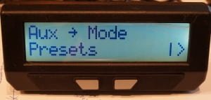
AuxPreset.jpg
With this option the auxilliary voltage input doesn't control a limit but instead lets you select the current preset with a remote toggle switch. With 3 presets enabled, then >66% VAux is preset1, 33-66% VAux is preset2, and 0-33% VAux is preset 3. With only two preset enabled, then anything above 50% VAux is preset1, while anything below is preset2. If you change preset modes on the fly, then the main screen will briefly display the new preset name for about half a second to let you know what's up.


Default Preset on Power-Up:
View attachment 4
Choose if the CA boots up into preset1 by default or if it loads the same preset it was in when it shut down.

New PAS Modes:
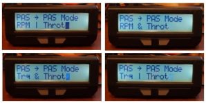
4 PAS Modes.jpg
For both the RPM or Trq control modes, you can choose whether you want this to be AND or OR'd to the throttle signal. Actually, that's not quite the case, in the Trq&Throt mode, pedaling without without the throttle will provide the assist, but if you throttle that only works while pedaling too. In both OR modes though, either pedaling without throttle or throttling without pedals will drive the bike.

Programmable PAS cutoff speed:
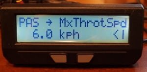
PAS ThrotSpeed.jpg
In either of the AND'd PAS+Throttle modes, you can set a maximum speed at which you can throttle without pedaling. So that should meet the varying legal pedalec classifications that have a maximum throttle-only speed. At the moment, once you exceed this speed and are not pedaling then the CA cuts out power abruptly, but I plan to have it use the smoother speed limiting PID loop in the future.

More info in PAS setup menu preview:
View attachment 1
The small 'P' and small 'D' both bounce up and down as the PAS and Direction signal alternate between 0 and 5V, and the current pas mode is shown as well

New Fast Ramp rate:
View attachment 5
Amberwolf, this one's for you! All the throttle ramps are now expressed in units of Second / Volt, so a higher number is a longer ramp time as had been often erreoneously assumed before, and it's in intuitive units. So if you set it to 2 seconds/volt, and your min to max output swing is 3 volts, then you know it will take 6 seconds to go from zero to full throttle.

The new 'Fast Ramp' option is a separate ramp up rate that the CA uses when it does not see any current draw. As soon as the CA senses more than 2 amps flowing from the controller, then it switches to the regular (presumably slower) ramp rate. Set correctly this eliminates the delay time that you otherwise need to wait if you have a slow throttle ramp but are already travelling at speed. The CA's output quickly gets to the point where it is drawing current, and then only slowly ramps from there on.

Having played around with this for a bit I can say I love it. It makes even a non-torque sensing PAS setup quite pleasant to ride. You can set a ramp time of like 3-4 seconds/volt which matches the natural acceleration of the bike, then taking off from a dead start it's exactly like what you do with the throttle, gradually ramping it up as you gain speed. But if you are already at speed and hit the throttle again, there is no annoying wait for the output to get to where it does something.

Finally, the setup menu preview for the throttle output also shows a little slanted bar graphic, and the faster the throttle ramp the steeper the slope:
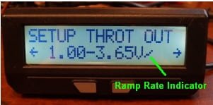
Ramp Rage Glyph.jpg

-Justin
 
rscamp said:
Would something like this work?
http://www.meanwell.com/search/apv-12/default.htm.
http://www.meanwell.com/search/PM-05/default.htm

Wonder of you could use the output from it to feed the THUN directly and also drive the CA. There are also dual output models too, but not yet found one quite suitable, there are so many to choose from on the site

Hey Neil, just catching up on this. Any of the above units or any 12V or so switching wall adapter will work for powering the THUN sensor from those voltages. If all you need to run from the 5V bus is a throttle then I wouldn't worry about powering the CA separately. At 84V it will be fine supplying the throttle, and at 134V you can glue a piece of aluminum over the CA circuiboard which will spread the heat away from the regular chip and it should cope OK too. The other possibility is just to use the controller's 5V supply, which can deliver the mA for a throttle and other 5V accessories easily enough.

-Justin
 
Great work Justin.

I know it's been answered before, but how many mA is the CA's 5v able to supply?
I am running 96v and am hoping to draw about 100mA without resorting to a dc converter.
 
Back
Top