Cycle Analyst V3 preview and first beta release

teklektik said:
NeilP said:
teklektik said:
... but at 134v you only have 2ma total (5v and 10v) current available - not even enough to run a hall throttle... (typically 5ma) so you will need to steal some 5v from the controller just to run your throttle (unless you have a Magura which only needs 1ma).
How would I do that? Can I just connect the 5 volt from the controller direct to the throttle input then? and output the hall throttle output direct to the CA.
Exactly. Pretty painless. You are good to run a hall throttle up to 100v, but you're a bit over the line....
from one page back...so you may get 6 or 7mA at 96 volts . So you are going to need a DC-DC convertor.

If I have understood teklektik correctly then anything much over 50 volts and you really need an external supply the built in one is not up to it for anything above the low voltage setups.

See the circuit teklektik posted on the last page. or search the meanwell site for suitable supply..or go the mini pc/notepad PSU route. it seems the only option till there is a hardware upgrade to the power supply side of the CA
 
shorza said:
Great work Justin.

I know it's been answered before, but how many mA is the CA's 5v able to supply?
I am running 96v and am hoping to draw about 100mA without resorting to a dc converter.
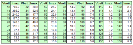
These tables are from the upgraded doc to be released shortly after B22. This should give you a notion of what the CA can support. The Aux Power jack doesn't count here - it supplies Vbatt.

Add up the combined current for both 5v and 10v accessories and compare with your pack voltage. If you are over the top you can:
  1. use the controller to power a 5v accessory or two using the controller throttle +5v pin
  2. power accessories from a DC/DC converter (e.g. Thun) or
  3. power the entire CA from a converter and set up the CA to monitor the pack voltage using a divider and the Vex input (see Advanced Features in the Unofficial Guide PDF).

View attachment 1
CAV3_maxCurrentVsVbatt2.png
 
If Vbatt is lower than 32 volt? what then?
What I am trying to find is the best voltage to run the CA at?. If one is to go out and buy a switch mode supply, then what is the best voltage to buy?
 
NeilP said:
teklektik said:
I still would like to see a switching supply instead,
Been lookign up switching PSU on the Meanwell site

Would something like this work?
http://www.meanwell.com/search/apv-12/default.htm.
http://www.meanwell.com/search/PM-05/default.htm

Wonder of you could use the output from it to feed the THUN directly and also drive the CA.
These are a very nice find - the first has very easy mounting. The 15v model of the first unit is only $10 from Mouser - which is unlikely to be the cheapest...

I will extend the table above to get down to 12v for the released doc, but even so can see that the CA alone it has a large capacity at low supply voltages.There is no reason to get tricky with splitting the power to run both CA and accessories - do one or the other. If you power the CA alone then you can then use unmodified CA connectors to obtain your accessory power as Justin originally intended.
 
NeilP said:
If Vbatt is lower than 32 volt? what then?
What I am trying to find is the best voltage to run the CA at?. If one is to go out and buy a switch mode supply, then what is the best voltage to buy?
Okay - I extended the table down to 12v.

As you can see, the numbers are insanely large at low voltages. I like 15v because it can run '12v' automotive accessories (iPhone, GPS, LED lights) as well. You can run that stuff on 12v as well, but on 15v, lights will be a bit brighter if you are planning on an automotive LED tail light. So - 12v vs 15v is sort of a call depending on the rest your build plans... Of couse, the CA Aux Power jack supplies Vbatt, so at these voltages, it's a handy place to plug in your phone with a little adapter or connector change.

To figure the excess power available from a converter if powering the CA, the CA draws about 10ma, so add that to your accessory requirements and whatever is left is available (well - leave a bit of a safety margin, but you get the drift....)
 
There are many many more..I started from this page,

http://www.meanwell.com/webnet/search/seriessearch.html

and selected initially by the lower power ratings
 
justin_le said:
Hey guys, I'm on the very last tweaks before going public with the B22 firmware, I just want to get a couple more days of folks here field testing so that we don't have any embarrassing bugs slipping by.

OK, so far it is looking alright. I've attached a B22_prelim version here. Super bonus brownie points to anyone finding operational bugs in the next 24 hours, and if nothing after that then I'll update the official website page with this firmware too.

[Edit: Updated attachment to perlim3]
 
justin_le said:
New Fast Ramp rate:
Amberwolf, this one's for you! All the throttle ramps are now expressed in units of Second / Volt, so a higher number is a longer ramp time as had been often erreoneously assumed before, and it's in intuitive units. So if you set it to 2 seconds/volt, and your min to max output swing is 3 volts, then you know it will take 6 seconds to go from zero to full throttle.
Thanks! :) That should be lots easier for most people to understand intuitively, requiring less support from you or others to figure out. ;)


The new 'Fast Ramp' option is a separate ramp up rate that the CA uses when it does not see any current draw. As soon as the CA senses more than 2 amps flowing from the controller, then it switches to the regular (presumably slower) ramp rate. Set correctly this eliminates the delay time that you otherwise need to wait if you have a slow throttle ramp but are already travelling at speed. The CA's output quickly gets to the point where it is drawing current, and then only slowly ramps from there on.
That should also be nice to have, and a more preferable way to deal with ramping up in traffic.
 
I just gave B22 a go. I wasn't able to enable the temperature sensor. Only the Max Temp setting was available in the menu.
 
rscamp said:
I just gave B22 a go. I wasn't able to enable the temperature sensor. Only the Max Temp setting was available in the menu.

I just tried it on two different CA's and it works fine. On the first screen where it says

Temp-> Sensor
Disabled

you should be able to press and hold the button for _OK to appear, and then toggle between disabled, 10K thermister, or linear type. Are you saying that you don't even see this "Temp-> Sensor" screen but that it jumps right to "Temp-> Max Temp"?
 
justin_le said:
rscamp said:
I just gave B22 a go. I wasn't able to enable the temperature sensor. Only the Max Temp setting was available in the menu.

I just tried it on two different CA's and it works fine. On the first screen where it says

Temp-> Sensor
Disabled

you should be able to press and hold the button for _OK to appear, and then toggle between disabled, 10K thermister, or linear type. Are you saying that you don't even see this "Temp-> Sensor" screen but that it jumps right to "Temp-> Max Temp"?

Yep. I don't even get the other options. Only Max Temp is available. I don't get the options to enable the other sensors either - PAS, Torque, Aux Pot. Maybe I should reprogram...
 
Just tried it again. No change. I did notice the programmer window was red and I didn't get ...PC Connected on the CA screen.
 
teklektik said:
No issues with B22 Setup. Just went through all options to update doc. All seems to work okay...
rscamp said:
I did notice the programmer window was red and I didn't get ...PC Connected on the CA screen[
Green = Good Flash.

It turns green only at the end. No problems with B20 and B21, although it is red when flashing B21 also and white when flashing B20.
 
rscamp said:
Just tried it again. No change. I did notice the programmer window was red and I didn't get ...PC Connected on the CA screen.

Hmm, that's funny. There are a set of mask parameters that aren't currently settable by pushing buttons which can be used to control which setup menu items do or don't show up on the navigation menu. So it seems like this part of the eeprom here didn't get filled with all 1's during programming! I think that because it's a full row of 0xFF's in memory that it's being treated blank data by the compiler and not getting saved into the hex file.

Try the prelim2 version where I've manually added a row of FF's to eeprom and let me know if that changes things for you.
 

Attachments

  • CA3_B22_Prelim2_NoCal.zip
    46.8 KB · Views: 89
rscamp said:
It turns green only at the end. No problems with B20 and B21, although it is red when flashing B21 also and white when flashing B20.
My Bad. I forgot that I have to use the old download program.
The behavior of the older version may be slightly different than the newer v1.1
Apologies for any confusion :oops:
 
That was it! Thanks Justin!
 
teklektik said:
rscamp said:
It turns green only at the end. No problems with B20 and B21, although it is red when flashing B21 also and white when flashing B20.
My Bad. I forgot that I have to use the old download program.
The behavior of the older version may be slightly different than the newer v1.1
Apologies for any confusion :oops:

No probs. All good now. I think... :)
 
Having some problems getting the PAS up and running with my RC friction drive setup. Basically everything works fine with the hall throttle but I can't get the PAS input to start the motor.

I have 5v and ground directly from the ESC to the PAS sensor with the signal wire going back the PAS solder pad on the CA. I am getting 1v at the PAS solder pad with the crank stationary with the voltage winding up to 4.2v when spinning the cranks quickly so to me this looks all good. However no output to the esc is achieved.

Setting wise I have the following.

SETUP PAS SENSOR
< 5P D (arrow up). P (arrow up)

PAS Quadrtr
Disabled

Start and stop delay unchanged

RPM Contrl

Throttle control mode is set to pass-thru

Any ideas.?
 
Kepler said:
Having some problems getting the PAS up and running with my RC friction drive setup. Basically everything works fine with the hall throttle but I can't get the PAS input to start the motor.

Setting wise I have the following.
SETUP PAS SENSOR
< 5P D (arrow up). P (arrow up)

Hey Kepler, this is where the preview screen here will be super useful. As you turn the pedals, do you see the arrow after the 'P' signal toggle between an up and a down arrow? This is an indicator of whether the CA sees what it thinks is a logic '0' or logic '1' on the input. I would have thought that 1V is low enough to trigger a logic '0' threshold, but if it's not consistent you could probably put a resistor to Gnd to help pull this voltage down further.

The up arrow after the 'D' means that you need to set the PAS-> Dir Plrty to be "5V = Fwd". Otherwise if you have it at "5V=Rev" it thinks that you are pedaling backwards when the direction pin is at 5V.

Let me know if that sorts it. With the direction polarity set correctly and the PAS input toggling you should be able to see your pedal RPM on the 3rd display screen and the PAS assist modes should work fine too. The default values for the Strt and Stop delay times are good for an 8 pole sensor, but for a 5 pole sensor you might want to increase them about 50% otherwise it will likely cutout when you are pedaling at a slowish cadence.

Now that I think about it, make sure you don't have a linear voltage PAS pickup that tries to emulate a 1-4V throttle signal rather than giving a pulse for each magnet passing. If so it's all but useless. I recall some of the early Crystalyte PAS sensors were like this which was necessary to interface with their old analog controllers.

-Justin
 
justin_le said:
Now that I think about it, make sure you don't have a linear voltage PAS pickup that tries to emulate a 1-4V throttle signal rather than giving a pulse for each magnet passing. If so it's all but useless. I recall some of the early Crystalyte PAS sensors were like this which was necessary to interface with their old analog controllers.

Note too, if that is the case, you can just use any speedometer pickup as the PAS sensor pickup instead. With two speedometer sensors side by side, one connected to the CA's direction input and the other connected to the PAS RPM input, then you'd have a quadrature signal going to the CA which would let it also distinguish between forwards and reverse pedaling. That is something that we plan to make at some point, a little double-reed switch PAS pickup that attaches to your downtube and lets you get the signals from any ring of magnets on the spindle, with no need to remove the crank arm etc. -Justin
 
Hello everyone, i am playing around with a hub motor and controller combo i got from John from CR a while ago that's running on 134V max and is pulling about 15kw after i modded the shunt. Atm the motor pulls like a tank up to 1/2 throttle and then it starts been jittery, surging a bit then it smooths out after the bikes accelerated a bit more and its fine. I have tried all the different throttle output options with out been able to get rid of the surging and if i set the throttle output to be 3V max it will sit in the surging speed range continuously. I don't know if this could be a problem caused by the CA or if it was my shunt modding as i installed both on the system at the same time, the shunt mod was done by wrapping 1/2 the shunt in copper wire then soldering over that to 1/2 the shunt value. I currently have a external 200A shunt that the CA gets its amp rating from. I have tried different ramp up settings on the throttle, if i lower it all the way to 100 it smooths out the surging slighly but its still very noticeable other then that i have not been able to have much effect on it.

Anyone have any suggestions on what could be causing the mid speed surging? Could cutting the shunt wires from the controller and wiring them to the external shunt have caused my surging? I have edited all the limit settings so they have no impact on the CA and none of them appear on the screen when riding at the surging throttle output. Atm CA is running as pass-through and just scaling the voltages to match, i am using a Magura throttle.
 
Is it possible to flash the CAv3 with a universal USB TTL converter or only with the special FTDI cable?
 
Back
Top