Shenzhen (ecrazyman) Controller Information

Tiberius said:
Running my motor/controller combination at "half" speed - ie., 36 V, full throttle - giving about 160 Hz rate on the Hall sensors. I find the following: As I reduce the clock speed it is ok down to 8 MHz, then the ramp on the motor drive disappears and it becomes a square wave. If I take the clock speed any lower, it all falls apart. The motor phasing goes wrong and there are nasty noises from it. On the good side, nothing breaks or catches fire.

At partial throttle much the same occurs.

Very informative!
It seems that the current limit in your PSUs prevent the damaging.
Wonder if you could also note the clock frequency at which the "squaring" starts?
Like to look at the traces when ready.
Thanks.
 
Cool.
Too bad your pulse generator doesn't go over 20mhz. I'd like to know how high it can go before it goes unstable.
 
Just a wild thought that ran through my head.. can we have the planet gears in the Bafang PMGR hub motors upgraded from nylon to -- whatever can/will handle ~110 pounds of thrust?
 
It is not the Bafang gears that worry me, it is the total mass of the motor. Because the rotor rpm is higher than a DD motor, a PMGR is generally more efficient. But never 100%. So heat will always be generated in the stator. But a DD motor has more mass of copper and is larger and can dissipate heat better than the smaller PMGR.

Motor_Sizes.JPG
Push either type motor too hard and, bammo! … Blown hall sensors. IMO the Bafang PMGR and Grubee DD motors should never be pushed beyond 72V & 30-amps. Even if you replace the wire harness with thicker phase wires (highly recommended btw. See ... http://endless-sphere.com/forums/viewtopic.php?f=2&t=4626), 2000W into the motor is about the max you can go without overheating the motor and blowing the hall sensors.
NEVER RUN THE BAFANG ABOVE 30 AMPS!

Hey, Maybe we should commission the Bafang Company to build a 5KW PMGR that we can push to 20KW! I'll put that on my girlfriend's bike (he he) along with some rockets!

I am diggin' Tiberius' pulse generator analysis. It is the final nail in the coffin to the demise of the mystery (i.e. the mystery is now dead and the solution is crystal clear).
Increasing the MCU clock speed is a no-additional-cost solution that will work 100% for the PUMA and most any other motor.
The code should be fixed also just because I abhor sloppy code (ahem ... Microsoft).
 
Stevil_Knevil said:
Just a wild thought that ran through my head.. can we have the planet gears in the Bafang PMGR hub motors upgraded from nylon to -- whatever can/will handle ~110 pounds of thrust?

P2 (solarbbq2003) using one metal and two nylon in the planetary gear seems to be an optimal choice.
The metal one could nearly transmit all the mechanical power from the sun gear to the ring gear.


The temperature of the outer hubs of both geared and gearless motors may appear to be the same.
But the winding in geared hub motor will be usually hotter than that of gearless hub because the rotor of the geared one is inside the outer hub (ring gear) while the outer hub of the gearless one is the rotor .
This would also mean that the Hall sensors in geared hub are also subject to a higher tempaerature.
 

Attachments

  • p2binner2small.jpg
    p2binner2small.jpg
    9.5 KB · Views: 4,269
Oddly enough, it was the steel gear in my P2A that failed (actually the bearings)! The two nylon gears were fine. This was after about 3 years of hauling a big guy on a trike! Tough little motor, but brushed. Sorry for the hi-jack!
otherDoc
 
The 24 Mhz 3 PIN CERAMIC RESONATOR off Ebay item no 270185419501 arrived this morning, fitted it and spent the next three hours taking the ecrazyman 48v/18a off the bike and wiring up 48v/28a. Works great no sync problem found at 19mph this time, Full throttle nls is now 27mph compared to 43mph of the 48/18a Ecrazyman Controller with pot, the toque is better and doesn’t appear to have any cut outs :) , but have lost around 7 mph off the top end road speed :cry: My batteries are low so will see if a full charge will help.


Thanks two all the people on this thread for there help in sorting out these controllers.
With a full charge 25mph and wheel spinning off th mark. :lol: Fantastic
 
aaannndddyyy said:
The 24 Mhz 3 PIN CERAMIC RESONATOR off Ebay item no 270185419501 arrived this morning, fitted it and spent the last three hours taking the ecrazyman 48v/18a off the bike and wiring up 48v/28a. Works great no sync problem found at 19mph this time, Full throttle nls is now 27mph compared to 43mph of the 48/18a Ecrazyman Controller with pot

This shows 27 mph with 24MHz is nearly proportional to 19 mph with 16 MHz.
Your top speed is still limited by the new critical frequency (say 487 Hz instead of 325 Hz).

The original "48/18a Ecrazyman Controller" does not seem to have such a critical frequency.
 
fechter said:
What motor are you using?
It`s an Ezee Sprint 2004 model 3 gears.
From the outside looks the same as a Crystalyte Motor.
http://crystalyte-europe.com.linux19.hostbasket.com/openhub.htm
It’s difficult to get accurate spec on this motor the legal wattage in the uk is 250w. Which is stated on the dealer’s web sites( 50 cycles), mine is an early model with no markings on it, and I think it’s a 500 watt brushless planetary gear motor.


Depends on which web pages you’re looking at some say 250w, some 350w, others 500w.
 
Here's a Thought for a DIY Project and everything is in stock right now.

PHASE I …

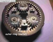
a) Buy a Bafang front PMGR motor (motor only) as cheap as you can from Keywin.
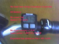
Tell him to add his stock (16-mhz) 72V controller (w/ 80nf10 fets) and a throttle too.

b) Order some 216mm spokes for a 26" wheel (like these ... http://www.amazon.com/Spokes-Wheel-Master-144-216Mm/dp/B000BMRS4S).
(Verification of the 216mm length is appreciated for one-cross spoke lacing. The motor spoke hole pattern diameter is 130mm.)
I determined the lace pattern and spoke length using AutoCAD. 216mm seems about right.
The motor reference drawing is here ... http://98.131.176.65/endless-sphere/QSWXBfrontwheel.pdf

c) Tweak the LVC (fechter style) and bypass the resistors to the voltage regulator cascade to suit your bat pack V (no mod needed for 72V).

d) Replace the 16-mhz resonator with a new 24-mhz resonator (looks easy now).
24-mhz replacement resonator is here ... http://cgi.ebay.com/ws/eBayISAPI.dll?ViewItem&item=270185419501&ru=http%3A%2F%2Fsearch.ebay.com%3A80%2Fsearch%2Fsearch.dll%3Ffrom%3DR40%26_trksid%3Dm37%26satitle%3D270185419501%26category0%3D%26fvi%3D1
20-mhz replacement resonator should also work for the Bafang ... http://search.digikey.com/scripts/DkSearch/dksus.dll?Detail?name=X909-ND
(or maybe just ask Keywin to upgrade the resonator to 24-mhz for free)

BTW ... PLEASE LEAVE SHUNTS ALONE! 30 amps is plenty for the Bafang ... IMHO

e) Lace the motor into your own 36-spoke 26" rim.

You have now invented your own little custom Bafang Front Hub beta test!
All that is left now is to monitor the motor temp, harness temp and tearing-it-up at 35 mph (72V and 30 amps).
And I am hoping that the motor will tear-up the road and not vice-versa.

Please Ride Responsibly!

PHASE II …

a) Buy a Bafang rear PMGR motor (motor only) as cheap as you can from Keywin.
Tell him to add his stock (16-mhz) 72V controller (w/ 80nf10 fets).
A second throttle is not needed.

b) Order the correct spokes for a dished 26" rear wheel (like maybe 214mm and 216mm).
(Verification of the specific spoke lengths for a dished rear wheel is appreciated for one-cross spoke lacing. Same motor spoke hole pattern diameter of 130mm.)
The rear motor reference drawing is here ... http://98.131.176.65/endless-sphere/7speedrearwheel.pdf
Add your own thread-on freewheel cassette (and maybe a rear disc brake too).

c) Tweak the LVC (fechter style) and bypass the resistors to the voltage regulator cascade to suit your bat pack V (no mod needed for 72V).

d) Replace the 16-mhz resonator with a new 24-mhz resonator (get's even easier the second time) or tell Keywin to do it for free.

Connect the two controllers to the same throttle.

e) Lace the rear motor into your own 36-spoke 26" rim.
The rear wheel spokes are dished (each side different length).
The center line of the wheel should align between the rear frame (142mm wide drop-outs) of the bike.

Rear_Hub.JPG
You have now invented your own little custom Bafang Front+Rear Hub beta test 2X2 Monster Bike!
All that is left now is to monitor the front and rear motor and harness temperatures.
And, of course, tearing-it-up at 'Ludicrous Speed' (72V and 60 amps total).
And I am confident that the 2 motors will tear-up the road and climb hills like a MF.

A 2X2 Monster Bike with two Bafang PMGR motors and two 72V 30 amps controllers and some serious Lithium.

Please Ride Responsibly!

PS If you want lifepo4 bats then ask Keywin for that too! All in one nice compact box.
(Just no rims. You provide the rims. You lace the motors. Smaller delivery box. YOU Save $$$.)
easy peasy! ha ha
 
Hi Knuckles,

That's not so far from what I'm doing. Except that I'm going for a rear motor and I will get someone else to lace up the wheel.

The idea is that it is a drop in replacement for the Crystalyte in 26" wheel that at this very moment should be en route from ebikes.ca.

When I've finished playing mix and match with the components, I shall assemble the parts (assuming they survive) into two bikes - one a full suspension MTB, the other a road bike.

Nick

Edited to add: Ooh look, its my 100th post. Time I had an Avatar

Edited again now Knuckles has posted PHASE II.

Well I could do this quite easily. The existing bike has a BAFANG motor on the front wheel, though its a 700c and a 26" rear wheel would look tiny in comparison.

Two motors would give twice the torque for hill climbing, but it may not add much to top speed. It depends whether the speed is limited by running out of power, or running out of volts. There is always the possibility of gearing the two motors differently and having one for low speed operation and one for high speed. It may be cost effective compared to switched gearing.

Nick
 
Nice Avitar. Aggressive Avitars Rule!
 
If you are advanture type of tester, I tested with 27MHZ Xtal, finally, It works.

My 16" bike run about 35KM/H (21MPH) @ 16MHZ on Flat
and now 58KM/H (36MPH) @ 27MHZ on Flat

P.S. I don't have 28MHZ Xtal to confirm that this mod is stable, You do it on your own risk. Good luck

Xtal from Digi_key
http://search.digikey.com/scripts/DkSearch/dksus.dll?Detail?name=SE3443-ND
 

Attachments

  • 27MHZ-2 Xtal.JPG
    446 KB · Views: 3,433
BOth for 60 volts

computerpc101 wrote:
My 16" bike run about 35KM/H (21MPH) @ 16MHZ on Flat
and now 58KM/H (36MPH) @ 27MHZ on Flat


Are they both using 48V battery?
 
Great work you've done here Knuckles!
Awesome QC from Fechter! and very good feedback from The7, Tiberius, etc...

Knuckles,
Can the Bafang front/rear PMGR motor be ordered with gearing made for high spped - 40mph, and run it at 72v or over? I'm planning to use both front and rear so torque won't suffer. Will the motor/controller(w/ mods) combo run reliable in this setup?
 
Hi Guys,

Well I must have some serious tasks today, because the displacement activities are taking over.
Here are some scope shots of the Shenzhen controller to explore the clock speed vs Hall rate issue. I reported on this a few days ago, and finally got round to the photos.

These are all using the Suzhou Bafang motor - nominally 36 V 250 W. It is 43 Hall pulses per revolution. There are photos of the test setup earlier in the thread.

In all shots, the bottom trace is one of the Hall sensors, the top trace is one of the motor windings to ground.
In one of the boxes to the right, the Hall rate is displayed.
These are all done with 36 V supply, to keep the energy down.
The normal clock speed of the processor is 16 MHz, these shots are done with the clock coming from an external source so it can be varied.
We know that it starts into trouble at 16 MHz clock, 325 Hz Hall rate, which with this motor is somewhere around 72 V.

First off, with full throttle.
There is very little effect as the clock rate is wound down from 16 MHz, then it suddenly happens.
36VFull8_1MHz.jpg
View attachment 3
Sudden change from 8.1 to 8.0 MHz. If the clock speed goes lower, the motor starts to sound bad.

With partial throttle the behaviour is a little different.
First shot is with 16 MHz clock and throttle adjusted for half speed
View attachment 2
Next at 8.0 MHz it is still behaving ok, but note the speed has increased
36VHalf8_0MHz.jpg
The rate can be reduced further, there is no sudden death, but at 5 MHz it has lost the plot and the motor sounds bad
36VHalf5_0MHz.jpg

So there you go. At full throttle the Hall rate that causes trouble is directly related to the clock speed.
The partial throttle test suggests that if we have the right clock speed to handle full throttle then it will also be enough for partial throttle.

Nick
 
More clock speed testing.

The next thing I tried was using a different signal generator to clock the processor, one that would go above 16 MHz.

The effect at 8 MHz with full throttle could be replicated. But I could not find an upper limit for clock frequency. There was no change as I wound the frequency up - I went up to 50 MHz and it didn't stop. Motor kept running and scope traces stayed the same as at 16 MHz.

I don't know the reason for this. It is possible that above a certain frequency the processor doesn't respond to a clock input and there are internal oscillations that supply a clock.

What it does do, though, is to make me wonder about the reports of it working with resonators and crystals above 20 MHz. Can we be sure it is actually on the resonator frequency, or is it ignoring it and self oscillating at a different frequency? That is actually quite common behaviour for crystal oscillators.

I'm not sure of the actual part number of the processor. What is the clock speed spec in the datasheet?

Nick
 
The actual processor is a bit of a mystery as the number does not come up on any searches.
Supposedly it is the same as a PIC16F72, rated for 20mhz.

One way to test the higher frequency is to give the controller a low input voltage low enough to trigger the LVC. The status LED will blink 8 times to indicate this. The higher the clock speed, the faster the blinks. If it's really running at 50mhz, the blinks should be so fast you can't count them :wink:
 
The old blinking light clock speed trick! I new it! I new it!
smart.jpg
 
Clock test

condition
36 volts LVC enable
- LED blink 8 time and pause one

No Xtal or Resonator
- no blinking at all

16MHZ Xtal or resonator
- LED blink and pause about 5 times @ 30 second

27MHZ Xtal or resonator
- LED blink and pause about 8 times @ 30 second

It seems that MCU responses to Xtal or resonator speed
- It might be that proble from single generator acts as resonator for low frequency

===============================================================
I am sorry that I don't have scope to measue motor Waveforms.

Another test - no loadl, Geared hub motor

Old controller Vs Shenzhen digital contorller @ 24MHZ
Condition
48 volts

Hall sensor = 200HZ
Half power
Older controller = 1.3A current very stable
new controller = 2.1A to 3.2A

Hall sensor = 470HZ
full power
older controller = 1.9 Amp very stable
new controller = 2.2A to 3.2 A

How come current is so unstalbe with this controller VS stable with old controller?
 
computerpc101 said:
Another test - no loadl, Geared hub motor

Old controller Vs Shenzhen digital contorller @ 24MHZ
Condition
48 volts

Hall sensor = 470HZ
full power
older controller = 1.9 Amp very stable
new controller = 2.2A to 3.2 A
Your test result using the old controller is same as mine using the analog C-controller on AL1020 e-bike tested in August 2007..
At no-load speed of 61 km/h, the frequency is about 540 Hz.
 

Attachments

  • 05-08-07_1013 copy.jpg
    05-08-07_1013 copy.jpg
    24.9 KB · Views: 4,168
  • 05-08-07_1014 copy.jpg
    05-08-07_1014 copy.jpg
    24.2 KB · Views: 4,165
This controller has " Self study PLC", It supposes to be better, How can we test it and prove this?

What Will " Self study PLC" effect on our measurement?
 
Back
Top