
For those who were wondering about Rotomax 150cc inductance, etc.
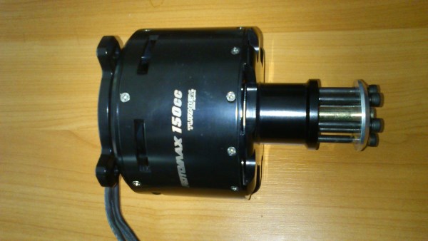
Received my rotomax 150cc today. Wires are a lot thinner than my old CA120, almost like 4-6mm². Phase resistance is 12mΩ; inductance 7.55-12.8μH depending on position. Cogging step is a lot smaller. Magnets thinner. Winding wires thinner. Stator slots shorter. It is ∆ wound. Bad thing about it that this part with 6 bolts is not removable, as in CA120.
Calculated values:
Power dissipation at rated 190A current: 433W (trapezoidal commutation, only in winding)
Power dissipation at rated 190A current: 325W (SVPWM commutation, only in winding)
Max RPM at 48V: 6860 (compensated on internal resistance)
Max theoretical power: 8.7kW
Max real power output: ~6-7kW
I did not have the time to look for suitable controller and just that one tiny 3s ESC was lying around. It did run fine at 12 volts.
Battery current 4A at 100% PWM 12V; 3.13A at 50%. Phase current 3.3A at 100%; 11.4A at 50%. Values measured with cheapo clamp meter and can be off.
It runs quite silently, as far as this ESC can drive. Reasonably well balanced. Looks well built.
Electrically 10 eRPM / RPM (however coggs 120 times per revolution). This means that controller has to work up to 70k eRPM to rotate this up to 7k RPM. Kelly with high speed option could be enough.
Magnet thickness 2.0mm
Back iron thinckness 2.0mm
Stator diameter 100.0mm
Air gap 0.5mm
Gap between magnets 3.3mm
Stator/magnet length 37.5mm
Gap between slots 2.5mm
Slot width 10mm.
1734 RPM @ 12V, so 144 RPM/V. Close to 150 as advertised
[moderator edit to consolidate data]
") . sry i could not measure inductance, still got no inductance meter. no load current figures look promising, guess we'll have a lot of fun with this motor series. hope i can come up with some measurement on the 80cc model sooner or later. it runs smoother than the older turnigys 80-100 IMO, nice to hear it's suitable for the kellys!
. sry i could not measure inductance, still got no inductance meter. no load current figures look promising, guess we'll have a lot of fun with this motor series. hope i can come up with some measurement on the 80cc model sooner or later. it runs smoother than the older turnigys 80-100 IMO, nice to hear it's suitable for the kellys!