GNG, 1000W 48V BB-drive, $400

I installed Lightningrod's plates today. To install the upper set I took off the large belt sprocket rather than the freewheel from the jack shaft. The belt sprocket came off easily.

How are people adjusting the belt tension once the jack shaft freewheel and chain are back on? I can only get to one of the adjuster bolts (and I've just stripped the thread on that!)?
 
t0me said:
I installed Lightningrod's plates today. To install the upper set I took off the large belt sprocket rather than the freewheel from the jack shaft. The belt sprocket came off easily.

How are people adjusting the belt tension once the jack shaft freewheel and chain are back on? I can only get to one of the adjuster bolts (and I've just stripped the thread on that!)?

It's difficult to keep everything tight and square at the same time while the bolts are tightened. I cut 2 hardwood wedges (about 30 degrees or so) and used one each side between ends of the motor casing and the metal housing for the jack shaft bearings. Don't tap them in too tight just enough to keep the belt tensioned.
 
I fitted Lightningrod’s adjustable side sheet kit; and I managed to cast the large pulley 172mm diameter 107T. The tooth profile is good but there is some runout of the large pulley sleeved on the original 80T aluminium pulley. I decided that I will add some bearings on either side of the belt to engage a couple more teeth on the small 18T pulley. I have gone up from the 15mm to a 20mm belt width on a HTD 580-5M-20 belt.

The casting made with a slow cure resin and aluminium powder filler; this has added about 300g to the weight of the 80T pulley.

I made some measurements of the unloaded motor and pulley compared to the original pulley setup
80/14T with very tight tensioner was 187W.
The new setup 107/18T no tensioner just adjusted with the Lighteningrod’s side sheets is now 67W.
That’s an amazing 120W improvement in power saving!

Here are a few pictures showing the casting of the pulleys; and the pulleys fitted on the motor/jackshaft setup with the Lighteningrod adjustable sheets.

Large pulley mould and casting
8625343104_fb2e10cac3_c.jpg

8625351284_2eb379a3f2_c.jpg

Small pulley mould
8631692820_0df91aba26_z.jpg


Pulleys fitted
8624244853_9511674000_c.jpg

8624240953_6c095c2bb6_c.jpg

8625347458_5f853bc0ee_c.jpg


More to come when I have completed the other mods to the belt tension, and enclosed the belt and pulleys. I think it will be a few days before I take it out for a trial run, but if the resin holds up under load, I hope it will all work OK.
 
Hello All,

While installing Lightning Rods top sheets, I'm at a point where I need a bit of help. The first is I do not recall where a part goes.... hate to say. Attached is the part; it's about 5/8" long; does not fit over the secondary side freewheel shaft.

Second, how is pulley elevation, relative to each other, adjusted? See attached. The 80T pulley is just less than 1/16" "higher" than the small steel pulley.

Thank you,
TomIMG_20130407_221242.jpg
 

Attachments

  • IMG_20130407_221443.jpg
    IMG_20130407_221443.jpg
    105 KB · Views: 5,682
  • IMG_20130407_221329.jpg
    IMG_20130407_221329.jpg
    92.5 KB · Views: 5,682
Hi redstone
That spacer will not fit without cutting it down when you have the Lighteningrod side plates. It fits in between the side plates and the support strap for the motor onto the bike downtube.
8631179951_c04c2c15b3_c.jpg
 
Ebikeman said:
I fitted Lightningrod’s adjustable side sheet kit; and I managed to cast the large pulley 172mm diameter 107T. The tooth profile is good but there is some runout of the large pulley sleeved on the original 80T aluminium pulley. I decided that I will add some bearings on either side of the belt to engage a couple more teeth on the small 18T pulley. I have gone up from the 15mm to a 20mm belt width on a HTD 580-5M-20 belt.

The casting made with a slow cure resin and aluminium powder filler; this has added about 300g to the weight of the 80T pulley.

I made some measurements of the unloaded motor and pulley compared to the original pulley setup
80/14T with very tight tensioner was 187W.
The new setup 107/18T no tensioner just adjusted with the Lighteningrod’s side sheets is now 67W.
That’s an amazing 120W improvement in power saving!
Thats a really impressive work on the pulleys. :shock:
How is the power saving data measured? Load or no load?
I'm afraid it needs to be measured when drive is under full load. When no load is applied will the tensioner take a huge preassure and therefore suck some power. When load is applied the belt will be a little loose on the tensionerside, because its fully streched on the other side. Thats my theory anyway. It would be the same logic with a chain, but not that big difference.
 
Ebikeman said:
Hi redstone
That spacer will not fit without cutting it down when you have the Lighteningrod side plates. It fits in between the side plates and the support strap for the motor onto the bike downtube.
8631179951_c04c2c15b3_c.jpg


Thank you, that helps a great deal. I could not find this part on Lightning's website. Since the alignment of my pulleys is off, I was thinking it made adjustments possible.

Any thoughts on pulley alignment adjustment?
 
Hi!

First post :)

Just wondering if there is a list of must do mods to get this kit to work at moderate powerlevels? I have been reading and reading this huge post and cannot make up my mind if it is worth taking the risk buying this kit because of all the problems. Say If I want to run it on 50V A123 up steep rough mountain tracks. What is minimum mods to get this kit to run somewhat reliably? If the Cyclone had not been so bloody noisy, that would be the obvious choise, now I'm leaning to a mid drive hub conversion, but the GNG looks much better... Can this kit be a reliable partner in the Norwegian mountains?

Cheers
Alex
 
arcticfly said:
Hi!

First post :)

Just wondering if there is a list of must do mods to get this kit to work ar moderate powerlevels? I have been reading and reading this huge post and cannot make up my mind if it is worth taking the risk buying this kit because of all the problems. Say If I want to run it on 50V A123 up steep rough mountain tracks. What is minimum mods to get this kit to run somewhat reliably? If the Cyclone had not been so bloody noisy, that would be the obvious choise, now I'm leaning on a mid drive hub conversion, but the GNG looks much better... Can this kit be a reliable partner in the Norweginan mountains?

Cheers
Alex

I think it really depends on what your definition of moderate powerlevels is as well as how you intend to ride. :wink:
 
For what it's worth, I actually got my credit card refund from the Mister Tao website. It was a small gamble when I placed that order, but I thought that folks would like to know for future reference that although I didn't get my motors, I also didn't get ripped off.

Now if only I could find that cheap source for just a motor, preferably with a plain shaft...
 
1500w?

Install GNG kit.
Remove the end of the controller (opposite from wires), apply a little solder at a time to the shunt (use a watt meter to check your progress while holding the brake on the back wheel to see what kind of amps you're now pulling). Stop when you get to 30A draw.
Screw the end plate back on.

Go play.

Oh and then consider a primary chain conversion cos if you're belt's not in good nick it'll likely start to skip.
 
Hi Christer
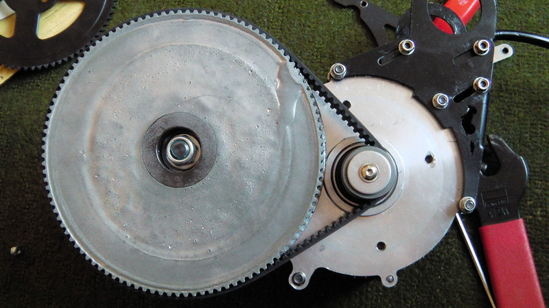
The power measurements were just to show the power loss being introduced by the original GNG belt tensioner; with its extreme wrap around the 14T motor pulley in an attempt to achieve more teeth engagement.

The motor was tested on the bench with no load on the output side of the jackshaft. I used my calibrated Cycle Analyst to measure the power. The initial power measurements were made with the stock 48V GNG controller @ 49V. I am now using 40V with a Greenbikekit 36-48V 9FET controller. The original setup power I measured is in keeping with full-throttle’s findings, posted last year, page 5 of this thread:
http://www.endless-sphere.com/forums/viewtopic.php?f=28&t=42785&start=100#p628795
I am not sure why the motor on its own should use such a lot of power.

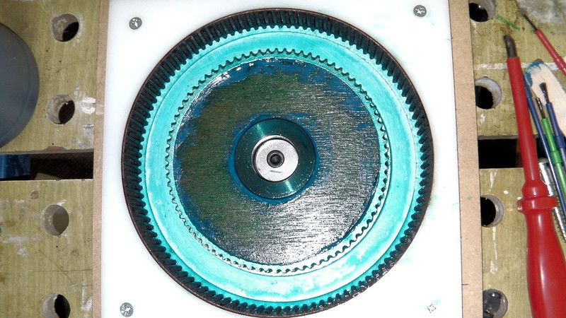
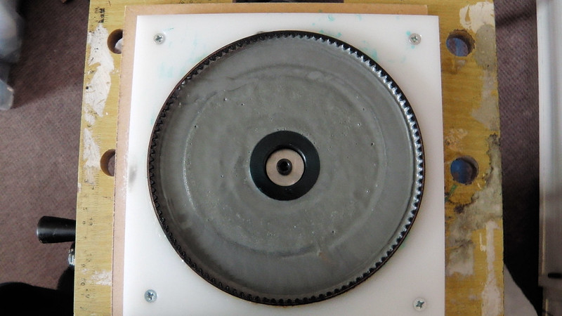
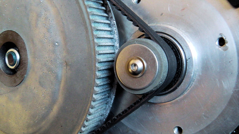
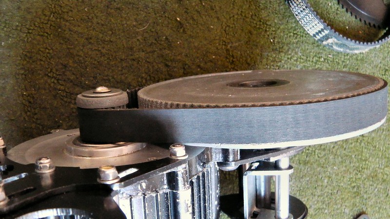
I am now seeing 1.7A @ 40V with the new larger pulleys and no tensioner. Using the LighteningRod side plates my belt is quite tight with only 1-2mm of play. But I have still to test all under full load.

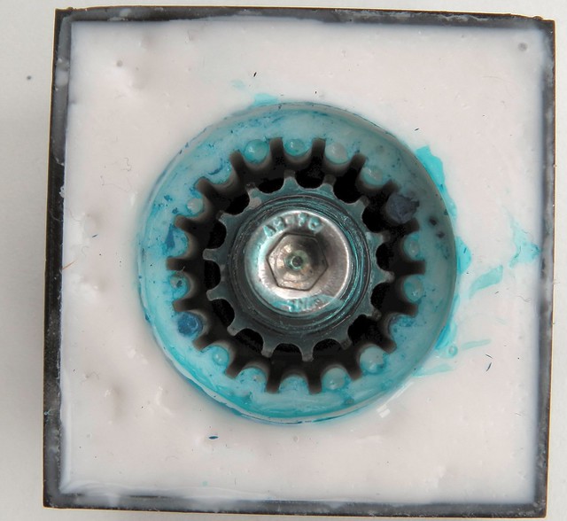
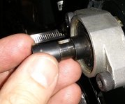
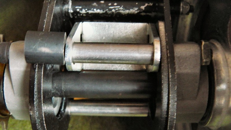
While I had the jackshaft disassembled to fit the new adjustable side sheets. I put 2 new good quality SS6201 2RS bearings on the jackshaft, and rebuilt the 12T freewheel with new (1/8” 3.17mm) ball bearings and grease.
It’s only a 2 pawl freewheel but there didn’t seem to be excessive ware on the ratchet teeth/pawls. Despite the fact that there was very little lubrication in the freewheel. I have only used the GNG kit for a few hundred miles, but I did note that some of the ball bearings showed signs of wear, with a grey colour. I suspect they are not hardened chrome steel, like the ones I have replaced them with. It all seems to run quieter and smoother now

And to redstone,
Re your problem with the miss alignment of the pulleys; I wonder if the jackshaft spindle has gone back and seated properly on the bearings; and have you tightened both the 80T pulley and the 12T freewheel nuts. The LighteningRod side plates should not affect the alignment of the large pulley with the motor pulley in that way; only the angle of the alignment if the jackshaft is not seated squarely on the side plates. As Mike describes on his tutorial web pages.

Spinningmagnets
Thanks for posting the link on the Re: GNG 450 brushless Mid Drive - Primary Drive Modification thread.
 
Had a few rides at 2000w with the 80:11 reduction primary chain mod and chain guide for the final drive now. The final drive chain no longer falls off, dropped the 2ndary chain once while jumping the bike so I'll definitely need to get the secondary adjustment sheets onto there to avoid that.

The reduction is much better like this, I can augment the power of the motor with my legs now and add a few km/h to my top speed and improve acceleration. I would go even higher if possible!

With this setup, I do have to shift a lot more because the motor "winds out" much faster in the lower gears. A smaller inner chainring on the bottom bracket would help relieve this a bit and give me a higher top speed, right?

I ordered some of those bottom bracket spacers, where do I put those in?

The bike is a blast with this setup and I'm probably going to throw another 500w at the stock controller and make a battery backpack to increase capacity.
 
A smaller inner chainring on the bottom bracket would help relieve this a bit and give me a higher top speed, right?

Go bigger on the inner chainring. If the 38T and 44T stock chainrings can have their locations swapped...I would put the 44T on the inner position, and the 38T on the outer. Then, I would find the biggest chainring I could fit onto the frame, and epoxy/bolt it to the side of the 38T (52T-60T?).

If the resulting ratio is too fast (hurting the hill-climbing ability), then you can use a larger gear on the rear. This is good because the more teeth that are engaged with the chain at the rear, the less stress is applied to each individual link/tooth.
 
I bought one used and set it up and was pleased with the speed and torque, but system shut down after coming to a stop on a 1/2 mile slight incline. Checked and giggled wiring seemed to get a twitch out of the motor applying the throttle, but only after rotating the motor pulley...but no motor spin. Any ideas?
 
intellibikes said:
I bought one used and set it up and was pleased with the speed and torque, but system shut down after coming to a stop on a 1/2 mile slight incline. Checked and giggled wiring seemed to get a twitch out of the motor applying the throttle, but only after rotating the motor pulley...but no motor spin. Any ideas?

remove the yellow rectangular connector with the 3 wires in it, i had that problem ant it was the connector,, no problem since
 
remove the yellow rectangular connector with the 3 wires in it, i had that problem ant it was the connector,, no problem since

I don't think that "yellow" connector itself should be a problem since it just provides protection for solidly bolting together the phase wires between the controller and motor. Having said that it's certainly possible that one or more of the spade connectors were poorly attached to the wires, in which case if another connector was used the problem would probably go away.
 
You need to get a digital multi-meter (DMM). They can be found for under $10, and they measure volts and amps. You can use them to test continuity, meaning that if there is a break in the line, no volts will make it through. It will show you which wire is not working, possibly from a loose connection or some other reason.

Y122KC.jpg
 
Could a mid-drive kit like this GNG one be adapted to my recumbent tandem?
BBTDM01_3.jpg
 
full-throttle said:
My controller is slightly different to denisesewa's but the technique is the same

The two red circles show R1 and R2. Ignore the unpopulated footprint in the top area of R1 for a moment, I'll get to that later.
The important bit is R1 is closest to the red wire and R2 is closest to GND.
LVC is simply a voltage divider that converts battery voltage into something the controller can read.
In this case the voltage divider is Vlvc = Vbatt x R2 / ( R1 + R2 )
Once this voltage drops to 3V the controller shuts down. Rewriting the equation above LVC will trip when Vbatt = 3 x ( R1 + R2 ) / R2
Notice R1 reads 1502 and R2 reads 1201. To get resistance simply write down the first 3 digits followed by zeroes equal to the last digit. Eq R1 is 150 0 0 = 15kOhm and R2 = 1.2kOhm
Substituting real values into the second equation LVC vill trip when Vbatt = 3 x (15+1.2)/1.2 = 40.5V

So to lower LVC to use with 36V one can either decrease R1 or increase R2.
To raise LVC do the opposite.

Now the tricky bit - to change LVC for a 36V pack simply solder an 0805 39kOhm resistor in the unpopulated footprint in R1 circle. That's it.
To raise LVC to 45V solder a 10kOhm 0805 resistor on top of R2.
This is great info. What about HVC? I'm trying to modify the controller to make it handle 18S, 72v. Changing FET's and the three 470uF capacitors. Maybe something more could be considered before applying the first test 72v?
 
flyingdutchman said:
I've contacted GNG and they supposedly have a chain drive retrofit they are working on....he admitted the belt was to weak. He sent a picture from the website of some guy with sprockets bolted onto the belt drive....looks pretty cheesy.

What ever happened to GNG's chain drive retrofit? :?:
 
christerljung said:
This is great info. What about HVC? I'm trying to modify the controller to make it handle 18S, 72v. Changing FET's and the three 470uF capacitors. Maybe something more could be considered before applying the first test 72v?
There's no HVC AFAIK.
To make it work on 72V you will need to change all the 63V caps, all the FETs, the LVC and the regulator. The latter can't have more than 37V difference between in and out. So those big through-hole resistors will have to increase in value. Double the ohm value, quadruple the power rating.
There could be more to it..
 
Back
Top