Experimental Cargo Ebike Trip, Vancouver to SF Maker Faire

LOL! I'm drooling at this charger. Which is OK, because it's built for it :p .

One word that describes your posts: INNOVATIVE. Pushing to the next level is your forte! I can't wait to see all these new morsels on your website so I can gobble them up.
 
justin_le said:
That brings us to the one of the other new pieces of hardware under field testing here, and one that's of fairly vital importance to ebike touring, the CHARGERS!! After over 2 years of R&D we're finally settled on what should be the final build details of the "Cycle Satiator - Universal Battery Charger".
I love this! :D
 
mushymelon said:
That charger is sweet, please tell me your prototyping high voltage ver as well.
Please

Just for you, mushymelon, we'll see what we can do ;). Actually, the reason the current release plan is for 60V max output has a lot to due with the UL certification, which is one of the other key features that I forgot to mention. Getting UL certification is a real bitch and puts a lot of creative limits on what you are allowed do, but on the other hand it's basically required for any kind of insurance protection. Things get in quite a different classifcation as far as allowable connectors etc. when you are dealing with 72V setups, and we'd need to find a way to work around that, plus we'd need to redo all the certification testing which is hideously priced.
 
These, Cellman's framefit battery, and a nice fast touring bike. Practical range limited only by how long you want to spend in the saddle. 8)

I'm going to have to be an awful good girl till Christmas! :mrgreen:
 
justin_le said:
Getting UL certification is a real bitch and puts a lot of creative limits on what you are allowed do, but on the other hand it's basically required for any kind of insurance protection...
I see from the pictures that on the charger cover you have puts both C and US certifications plus a CE mark indicating compliance to European safety legislation. What EN standards have you planned to comply to? It would be nice if you cover enough to fulfil the charger requirements in EN 15194 - European assisted ebike standard. Then your charger can be an integral part of the ebike.
 
I believe the vast majority of current and future E-bike buyers are not posters on forums. They want their E-bike to be an "appliance" like a microwave. After you buy it, you just plug it in and it simply works, with no "microwave chat forum" postings necessary.

Towards that end, I can foresee 36V/48V continuing to be the meat-and-potatoes of the E-bike market, for retailers who wish to survive in a very competitive business. the form factor of this charger is great, and having the hot components bonded to a thick aluminum shell is perfect.

I actually like the smooth body on the charger, Justin. You might consider having a rectangular fin-set as an option, which would be very easy for customers to epoxy to the shell. Even if it's not really necessary, it would save customers who want that...from needing to shop around for the perfect size of finned heat-sink. If all the chargers came from you as finned, it would be awkward for the customer to cut them off if they wanted a slimmer profile, so a smooth case is the best starting point. I love the charger.

Since charging is done when parked (no airflow), I recommend an enshrouded fin-set as an option. If mounted near vertical, it would create a heat-chimney effect, or you could take infra-red pics of two of them side by side, one with chimney-fins and one with none. Visualize bonding a rectangular aluminum tube to the flat exposed part, and the interior of the rectangular tube is filled with a common finned heat-sink.

edit: all ideas posted in this public forum by me are given freely as a gift to the public domain, to be used by anyone for any purpose.

31dYmJc8FvL._SL500_SX160_.jpg

2001_February_a1_f3.jpg
 
justin_le said:
At the same time, we were also exploring ideas of implementing a right side drive option for the stokemonkey, which could look cleaner, and could also enable the use of a THUN torque sensing bottom bracket. With a normal stokemonkey setup, the torque of the motor goes through the spindle and so wouldn't be differentiable from the the pedal torque.
Although you could still (in theory) setup a control loop for throttle that used the *change* in torque to control power to the motor.

If torque decreases, power can be decreased. If torque increases, power can be increased.

The catch with the latter part is that unless it periodically (frequently) cut motor power just long enough to check for continued torque input from the pedals, it would never stop applying more power until the vehicle was at a fast enough speed to relieve the torque on the system....

Since I am still mostly asleep I'm not sure listening to me is a good idea right now. :oops:
 
For those who don't know about the EBike Nerd Podcast, Justin talks a lot about this charger in the Ebike Nerdcast, Episode 20, and shares some great details about the motor as well in episode 21 (the three part series, episode 19-21 are a must-listen, as are basically all the episodes).

Thanks Troy and Greg for hosting a great show, and Justin for sharing so much knowledge!
 
Ypedal said:
any chance these chargers will play nice while in series? ... say you want to run a 24S lipo pack, set 2 chargers to 50.2v , wire in series and bob's your uncle ! ?... a guy can dream. :p

Yup, this is usually only a problem when you have chargers that connect the output ground to the charger casing, which unfortunately was the case with a lot of the high power brand devices as many have found out the hard way. Usually when you series connect isolated power supplies into a single output you want to tweak the settings so that one of them is in constant current mode and the other is in constant voltage mode, and then the control behaviour is more predictiable. So if the goal is 100.4V, you'd put one at say 51V 7A output, and the other at 49.4V and 8A. The latter is then always in constant voltage for the whole cycle, while the first charger is responsible for the regulating the switch from CC to CV behaviour.

If you have two 12S tap points on the pack, then things are easier and you just plug each charger into that with the 50.2V setting. The fact that the packs are series bridged is immaterial.

-Justin
 
spinningmagnets said:
I actually like the smooth body on the charger, Justin. You might consider having a rectangular fin-set as an option, which would be very easy for customers to epoxy to the shell. Even if it's not really necessary, it would save customers who want that...from needing to shop around for the perfect size of finned heat-sink. If all the chargers came from you as finned, it would be awkward for the customer to cut them off if they wanted a slimmer profile, so a smooth case is the best starting point.

It sounds like you've been eavesdropping on all of our planning meetings! That was _exactly_ the scheme we had in mind with this redesign. You can't see it too well from the pictures, but in the section view here you can see that on the ends we've left an undercut section that should make it easy to have a simple clip-on clip-off heatsink option:

Charger Section View.jpg

Before that we had designs with various threaded holes and such for a screw down heatsink, but that breaks otherwise smooth uninterrupted top surface which we became attached to.

As it is, even with no fins the chargers can do full power in a room temperature ambient environment without hitting thermal rollback, with the case getting to about 60-65oC. But if you are in a hot climate that is like 40oC out, then it would likely reduce the maximum power unless additional fins or air flow cooling was added. With fins we could probably bump the power to 400 watts as well, rather than 360W.
 
do you use a thyristor to make it a universal voltage charger? from 90V-270V like kingpan started doing with their small chargers?

i have seen a number of failures on the thyristor daughterboard on these 'universal' voltage chargers. mainly the small 35V cap in the corner of the daughterboard and i do not understand why they fail.

in europe where they use 2 wire 240 circuits there have been failures of this thyristor based design when the circuit cannot find a ground to use for controlling the thyristor switching so it may be something to examine further in your life cycle testing before release.

i have recommended to both ping and jimmyD that they avoid these chargers. ping told me he is plagued by warranty calls on these chargers since kingpan decided to follow this method to provide 'universal' voltage use.

love all your work and wish you the best. lemme know if you have problems in oregon or washington, and i can come out and sag you guys back to portland until you get things fixed. rassy is down south and others in northern california could sag too i bet.
 
dnmun said:
do you use a thyristor to make it a universal voltage charger? from 90V-270V like kingpan started doing with their small chargers?

No, it's a dedicated PFC front end that takes any input AC voltage and steps that up to a 400V DC bus, so there is an entirely separate set of transformers and transistors tracking the AC input and converting it to the DC bus voltage. That's the spare no expense approach to working off universal line voltages, and the goal was to make a "spare-no-expense" charger. But at higher power levels like this, the power factor corrected input is good practice and I believe even a legal requirement in the EU. Power supplies that just diode rectify the AC line into a capacitor bank don't play very friendly with the power grid.
 
justin_le said:
As it is, even with no fins the chargers can do full power in a room temperature ambient environment without hitting thermal rollback, with the case getting to about 60-65oC. But if you are in a hot climate that is like 40oC out, then it would likely reduce the maximum power unless additional fins or air flow cooling was added.

Or a damp cloth? :?
 
justin_le said:
...the power factor corrected input is good practice and I believe even a legal requirement in the EU.
Yes, in the EU all electronic devices connected to mains and consuming more than 75W need to comply to the standard EN 61000-3-2: Electromagnetic compatibility (EMC) Limits. Limits for harmonic current emissions (equipment input current ≤ 16 A per phase)
With a suitable PFC harmonic current levels will be within regulations. There are a few exceptions but it is unlikely that a 360 W ebike charger falls within those exceptions.

Here are two documents describing the technical requiements in this standard: http://www.epsma.org/pdf/PFC Guide_November 2010.pdf and http://www.teseq.us/us/en/service_support/technical_information/05_AN_IEC61000-3-25.pdf

In the European ebike (Pedelec/EPAC) standard EN 15194:2009 the following European standards apply, see section 4.2.5.3 Battery Charger:

EN 55014-1 - Electromagnetic compatibility - Requirements for household appliances, electric tools and similar apparatus -- Part 1: Emission
EN 55014-2 - Electromagnetic compatibility - Requirements for household appliances, electric tools and similar apparatus -- Part 2: Immunity
EN 61000-3-2 - Electromagnetic compatibility (EMC) Limits. Limits for harmonic current emissions (equipment input current ≤ 16 A per phase)
EN 61000-3-3 - Electromagnetic compatibility (EMC) - Part 3-3: Limits - Limitation of voltage changes, voltage fluctuations and flicker in public low-voltage supply systems, for equipment with rated current <= 16 A per phase and not subject to conditional connection

EN indicate EU-specific standard but I believe all of these are identical to IEC standards with the same number.
 
count me in for all three as well :)

i remember that finned charger from the show (you had that proud new father grin) :wink:

you're gonna need a bigger booth this year!

if you need to rent some scantily clad azian sho-gurls to sho ur stuff u know who to call.

liveforphysics said:
3 new must-buy items for me.
:)

That's a beautifully packaged dense power component layout, and a wicked little useful display setup. Killer job my friend!
 
JennyB said:
justin_le said:
But if you are in a hot climate that is like 40oC out, then it would likely reduce the maximum power unless additional fins or air flow cooling was added.
Or a damp cloth? :?

Yes of course that would do the trick too, there is always a poor-man's solution to every problem that works just as well :wink: Kindof like the amazing effectiveness of garbage bag ponchos, or duct-tape wallets...
 
The last part of the puzzle was the batteries. In starting this trip, we were each using 4 of the flat-pack 48V 10Ah eZee batteries, 13S 5P of 2200 mAh cells apiece, for 48V and ~42Ah of actual capacity. The edgerunner frame neatly accommodates one battery under the rear deck, but we wanted to move most of the remaining packs up towards the front of the bike to even out the weight a bit. We thought they looked pretty good on either side of the frame, like small gas tanks, but they were wide enough to interfere with our knees while pedalling. So kept moving the mounting point forwards and up until finally there was clearance, but by that point they protruded front of the frame in a goofy manner and were high enough to exacerbate the tippy handling on some already top loaded bikes.
High Front Batteries.jpg

So, when we got through seattle we picked up a front bike rack from REI, and then moved the battery anchors down onto that instead of on the frame. Though I knew the lower CG would be good for handling, I thought it would be a disadvantage having the battery load pivot with the front wheel. To my surprise I found it gave a huge improvement. The extra inertia on the front wheel completely eliminated the low speed front wheel wobbles that were present with the pack on the frame, and it gives some feeling of tank like stability to the whole affair. Hands free riding was certainly not in the cards in the original layout.

View attachment 5Hands Free.jpg

It was also a good way to test out the twist battery anchors that we'd made for these packs. Our initial designing was based on the idea of the battery sitting horizontally on the rack, and we weren't totally sure just how well they'd hold up with a sideways loaded assembly. There was a little bit of play on one of the packs which would cause a bit of rattle on bumpy roads, so I used a bungee to hold it snug, and with that's it's been quiet and solid.

Anyways, the original plan was not to run four 10Ah packs which is a bit cumbersome, but two custom laid out 20Ah allcell batteries instead. As most of you are familiar, AllCell is a battery assembly operation based in Chicago who use a phase change material between the cells in order to clamp the temperature rise, and in theory the lower peak temperatures should increase the cycle life, and potentially allow the use of the lower cost / whr energy cells rather than the power cells we'd usually spec in an ebike.

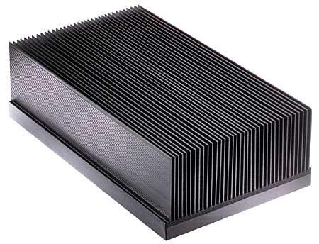
We approached them with a healthy dose of scepticism since their marketing material read like the typical over-the-top wonder battery claims, and included life cycle graphs that looked more like they were produced in photoshop than on a lab discharge station. But last year they made us a pack that had the exact same cell layout and cell type as our eZee flat packs, enabling us to do a side by side discharge comparison. And sure enough, on a 2-3C continuos discharge setup, the eZee packs would hit 65oC right in the space between the cells, while the allcell pack with PCM surrouding never went above 45 degrees.

Even more intriguing though was the additional protection and ruggedness that the PCM matrix provides by surrouding all the individual cells. We'd had many problems in the past with heatshrunk batteries mounted to bikes or racks that eventually wore through the heatshrink at contact mounts and in some cases caused a short circuit, and in other cases denting and cracking the cell case. This was especially true with attempts at doing frame mounted batteries in soft bags. But the allcell technique there is a safe buffer of PCM material before any cells are exposed. After cardboard and wooden mockups we came up with this layout for the cells, which could be configured in either a 10S 9P or a 13S 7P layout:
View attachment 1

The cavity on the bottom left is to provide a protected space for the BMS circuitry so that the circuitry sit's flush and isn't vulnerable and protruding through the shrinkwrap, and the the geometry made up such that it should fit inside the small and medium sized Revelate Tangle Frame Bags and tapered with an acute angle to fit in the front triangle of most bikes OK.

Allcell wasn't quite able to get these packs made in time for our departure, but they did rush them through to get to Wake at TheEbikeStore in Portland so that they showed up during our Portland stay. Scott at AllCell warned that they might look a bit ugly given that it's hard to shrink over a taper, but to us these were things of beauty! First check to see if they fit the tangle bags OK:
Battery in Revelate Bag.jpg

And then more importantly, did they fit in the edgerunner frames? It was tight, but with the downtube cables arranged neatly everything fit just so:
48V 17Ah In Frame.jpg

We got three of these packs in total, nominally 48V 17Ah each, and left behind four of the 48V 10Ah eZee packs with Wake. So each bike now has more capacity, and with the weight centered in the frame and no longer taking up cargo space.
 
I keep repeating to myself: "thou shalt not covet thy neighbor's e-bike."

But you keep posting more awesomeness. So I covet. I covet but good!
 
Justin--with all the new options, I wonder about adding another. Would it be possible to hack a Timex heart rate monitor watch, and link that into the Cycle Analyst to set parameters for the rider's heart rate? For example--if my heart rate dropped below 130, the electric assist would decrease the amount of assist. Then, if my HR increased above 150, the electric assist would be 100% throttle on. This would be cool to ensure e-biking would remain good exercise, and it might be good for my patients after they leave the ICU--their cardiac rehab therapist could prescribe a set heart rate riding range so they could have fun without (hopefully) having another myocardial infarction. Maybe an e-bike could even be prescribed and paid for as medical equipment under the medical insurance plan!
 
Justin, I was skeptical about AllCell, but I trust you. Even if some company exaggerates their products performance, if the actual performance is better than the competing products, it is worth keeping an eye on.

I have not heard from DocBass about testing the NCA cells I sent him recently, I hope they arrive soon. This is very good news for me about AllCell and the PCM material. Ire call reading that at the absolute hottest an E-bike battery would get, the PCM material would be soft enough to show a fingerprint when pressed, but would not "melt".

(runs off to find link)
“…The wax is micro-encapsulated within the graphite matrix. When the wax melts, there’s enough surface tension between the wax and a graphite matrix that it doesn’t leak out. You could heat the material up to 300C (570F), and it will become soft enough for a thumbprint, but it will remain solid…”
 
I had my first chance in three years since getting my e-bike set-up to ride with other e-bikers--and I got to ride with Justin and Robbie. They arrived to my house at 7 pm Monday and greatly impressed my kids with the electric skateboard. When my son mentioned that he wants to be a mechanical engineer, and Robbie said, "that's what I am," my son was super excited. After a dinner of wood-fired-outdoor-home-build-adobe-oven baked pizza, and a short break, I was able to set off with Justin and Robbie south to Woodland, WA along the route of my 38 mile commute to Longview, WA. We rested/charged batteries in Woodland, then continued to Wake's (of the E-Bike Store) in Portland. It was such an awesome ride. I charged at Wake's, then rode home. I had to stop in Longview to charge for 2 hours, and I made it home at 0130 in the morning on Wednesday. It was a record for me--180 miles on 2.5 charges in 24 hours. I wish I would have taken more pictures. Thanks so much Robbie and Justin--and Wake.
 

Attachments

  • Justin at Wills.jpg
    Justin at Wills.jpg
    21.4 KB · Views: 5,779
  • DSCF0931.JPG
    DSCF0931.JPG
    12.8 KB · Views: 5,779
Back
Top