Cycle Analyst V3 preview and first beta release

Configurable AuxPot 3-Position Switch Using Fixed Resistors

This describes how to construct an AuxPot 3-position switch to limit any of: Current, Power, Speed, or PAS Assist. The switch selects one of three percentages of the configured limiting parameter: (high, med, low) = (100%, Lmed, Llow) e.g. (100%, 66%, 33%). Although fixed resistors are used, a wide range of Lmed and Llow values can be configured using Setup.

Theory of Operation

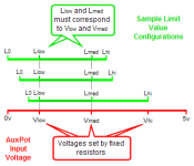
The idea is to establish fixed switch-selectable voltages but shift the endpoints of the allowable AuxPot input voltage range to alter the way those voltages appear relative to one another and to the overall AuxPot range.
  • In the illustration below, the red portion shows the maximum AuxPot voltage range and several voltages determined by fixed resistors.
  • The green scales show three different possible working ranges of AuxPot input as determined by (AuxMinIn,AuxMaxIn). Although limits Llow and Lmed are bound to fixed voltages, the overall green scale can be shifted left or right or expanded or compressed by moving the endpoints - this changes the relative position of Llow and Lmed in that range and thus their effective values. So - it's all a matter of point of view....
  • The relative values of the fixed voltages also impose certain limitions on the possible Limit Value configurations. The trick is to pick voltages that will allow a range of commonly useful limit settings.
  • LMH-FixedR-Adj-Oview2.png
Fabrication

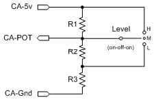
The switch is wired as shown below. For accessory current inventory purposes, this circuit draws a maximum of 0.53ma. The switch can be any center-off SPDT toggle or rocker switch - or any of the commercially available ebike 3-position switches. Current is very low - resistor wattage can be anything available (1/8W, etc).

  • LMH-FixedR-AdjAuxMaxIn+AuxMinIn.png

This can be fabricated many ways, including squeezing the resistors into the side cover of common 3-speed ebike switch. However, an easy technique that is pretty stealthy is to cut the cable of an ebike 3-speed switch and splice the resistors in-line. Choose some part of the cable run that is relatively straight and will not be subject to flex. Leave the end resistor leads a little long and spiral wrap the whole thing with waxed dental floss (DIY cable lacing twine) out to the end of the resistor leads so they are bound to the insulated cable wire for strength. Sleeve with a couple of layers of heatshrink.

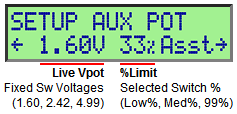
Before you add the outer heatshrink, verify the pin-to-pin resitances below with a meter for the three switch positions. Then plug the cable into the CA, navigate to the Setup AuxPot Section Preview screen and check that the voltages are as shown in the table for the three switch settings. If all is well, apply the outer heatshrink. :)

  • TestMeasurements.png
    AuxPot-3PosSw-PreviewScreen.png
This printable PDF has the images above for bench use.

Configuration

  • AuxPot-FixedR-3PositionSw-ES_1-3_iv450.jpg
  1. Set appropriate Setup parameter (e.g. PLim->MaxCurrent, PLim->MaxPower, Pas->PasWatts) to desired maximum value.
  2. Determine LowLimit% = ( LowValue/MaximumValue)*100.
  3. Determine MediumLimit% = (MediumValue/MaximumValue)*100.
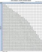
  4. Locate proper cell in table at (col,row) = (LowLimit%, MediumLimit%)
  5. Transfer cell values to Aux->AuxMinIn and Aux->AuxMaxIn.
  6. Go to Setup AuxPot Section Preview screen, verify switch settings (L,M,H) display limits of (LowLimit%, MediumLimit%, 99%).
  7. If limits are not exactly as desired, then locate the appropriate adjacent cell and modify both AuxMinIn and AuxMaxIn toward those new cell values.
Note: Altering the maximum limit value (e.g. PasWatts) will result in proportional changes to the medium and low limits.

This is a printable PDF of the settings table for shop use/road adjustments.

For example, to set up the switch for PAS Assist at levels (750W, 450W, 250W):
  1. Set PAS->PASWatts = 750W
  2. LowLimit% = 250W/750W x 100 = 33%
  3. MedLimit% = 450W/750W x 100 = 60%
  4. Look up row 60%, column 33% in table. Use nearest cell (60,32) and get (0.65, 3.57)
  5. Go to Setup PAS section
    • Set AuxMinIn = 0.65, AuxMaxIn = 3.57
    • Go to PAS section preview screen and operate switch - Asst% should show (99%,60%,32%)
Grin Tech 3-Position Switch

There is a new Grin Tech 3-position switch that prompted this post - it uses the identical fixed resistance/adjustable min/max strategy, but with a slightly different four resistor circuit. The fixed voltages are: (L,M,H) = (1.66v,2.50v,3.33v). The 3-resistor circuit presented in this post appears to provide a bit wider adjustment range (I have an email out to Justin about this).

This is a printable PDF of the settings table for shop use/road adjustments for the Grin Tech 3-position switch.


Operation as a Preset Switch

This ES switch can be used as a 3-position Preset Switch by setting (AuxMinIn, AuxMaxIn) to (2v, 3v).
The Grin Tech switch can be used as a 3-position Preset Switch by setting (AuxMinIn, AuxMaxIn) to (1v, 4v).

EDIT - This information is now part of the Guide.
 
justin_le said:
Doctorbass said:
justin_le said:
(don't you tell me it needs one more digit ;) )
I can count 7 more free digit on the 2nd line.. leaving enough space for displaying 90 000 000 000Watts (90 Gigawatt) :mrgreen:
Doc

Ha, you guys are all a little crazy. Good news is that now with the bootloader we can do a custom "DoctorBass" firmware mod that anyone can install which will show all your power stats in gigawatts, your distance in light-years, and your speeds measured in units of c (as in 3x10^8 m/s). The day your ebikes become certified rocketships, the CA will be there for the ride... -J

HELL YEAH, when someone asks how fast it goes we can give it to em in LightSpeed :) Now that's convincing for how fast a bike it when you have to shift an entire scale ie: mph to lph

-Mike
 
teklektik said:
Adjustable AuxPot 3-Position Switch Using Fixed Resistors

Teklektik, you are the greatest! Now even electrodummies like me can do it! Many thanks!
 
I have an idea that i have just put into a furmular format on another thread, but wanted to share it here becuse i think it would be a valuable addition to the Cycle analyst, maby the next incarnation...
the idea is that for the low speed section of the motor it will be restricted to low power and gradianted up from a given speed to another given speed to a high power limit
eg 1kw lower than 5 kph and gradient from there to 3kw at 15kph so while the motor is in it heat producing ineficient stage it will be automatically ramped down, this would be ideal for high voltage / high speeed motors IMO
here is the code idea:
if speed <=Speed1 then powerLimit = lowlimit
If speed >=Sspeed2 then powerLimit = highlimit
else powerLimit = (speed-speed1)/(speed2-speed1)*(highlimit-lowlimit)+lowlimit

btw it took my about 20mins to work out that equation. i think it's right but please correct me.
 
I have a few issues with the v3 at the moment (running the latest beta).

Ever since the release just before the beta, I have been getting 'spikes' registering as the max speed, eg 398km/h. I am using the separate speedometer sensor as I'm running a Mac/12 fet controller from Cell Man.

The second problem is that I rode in the rain today for the first time in a while and now the CA is reading the current/power wrong. Sometimes it works, but mostly it doesn't and it's claiming negative power - except regen isn't possible with this setup anyway.

I opened up the CA, but it didn't really look wet inside. The wiring is dry too, so I'm not sure what the problem is. Do I have an issue with the controller? Moisture in the controller? The bike works fine otherwise.
 
I know that you can use the THUN X-Cell RT with the Cycle Analyst V3 10 Volts internal power supply, at least up to a nominal 48 Volts system voltage. With a higher voltage you must use an external 12V power supply :| to run the THUN X-Cell RT.

Now what if I have a 48 V System Voltage, but using it with an Infineon controller that can handle a system voltage range between 36 and 72 Volts, hence has a regen Voltage of up to 84 Volts :shock: (say on a longer downhill road).

Will that damage the Cycle Analyst V3 :roll: :?:

Did anyone have a 'practical' experience?
 
electricwheels.de said:
I know that you can use the THUN X-Cell RT with the Cycle Analyst V3 10 Volts internal power supply, at least up to a nominal 48 Volts system voltage. With a higher voltage you must use an external 12V power supply :| to run the THUN X-Cell RT.

Now what if I have a 48 V System Voltage, but using it with an Infineon controller that can handle a system voltage range between 36 and 72 Volts, hence has a regen Voltage of up to 84 Volts :shock: (say on a longer downhill road).

Will that damage the Cycle Analyst V3 :roll: :?:

Did anyone have a 'practical' experience?

No practical experience here, but I don't understand the problem. With a 48V system (12S Lipo?), I would program the controller to provide me a maximum of 12*4.2V= 50.4V regen. This way I would not be afraid of damaging neither my battery, nor the CA.
 
I would have done that, too.
But the controller is the new type Infineon (the one with the blinking LED in the side panel) C7240-NC and has a new type board. I have asked Justin early April about the R12 Resistor:
Question: brake regen - The old controller had a 2.4 kOhm resistor to go with a cutoff voltage of 57V. By replacing the R12 resistor with a 1.6 kOhm, the cutoff voltage could be risen to 84V.
The new controller has a 302 resistor (R12), meaning 3 kOhm. What's the cutoff voltage relating to this value and what resistor do you recommend for taking it to the 84V cutoff voltage?
To which Justin replied:
Regarding regen, they should still work up to ~85V since that is our required spec. I haven't reverse engineered the layout on the new boards to confirm which set of resistors is now used for the voltage sensing if that has changed. Are you having issues doing regen with it at the moment?
I have not heard anything from him since.
 
Are you saying that you cannot lower the regen voltage using the keywin or XPD software for this controller? You should not need to do the R12 mod to lower regen voltage....
 
I would say yes, because I don't think that the CA will distinguish between battery voltage or regeneration voltage. I blew up my CA when I connected it to my 20s 84v pack. I had to send it back to Grin for repair.
 
Merlin said:
84v blewed CA? why?!
cannot be the voltage....
My response was in light of having the Thun connected at various pack / regen voltages. As Justin mentioned, the CA cannot provide the Thun with the 10 volt that it needs. I found out the hard way.
 
Architectonic said:
Ever since the release just before the beta, I have been getting 'spikes' registering as the max speed, eg 398km/h. I am using the separate speedometer sensor as I'm running a Mac/12 fet controller from Cell Man.
This is almost certainly due to contact bounce in the pickup. The rapid pulses from the bounce make the CA think the wheel is spinning very rapidly. Any pickup from a cheapie bike computer will work, but you might contact Grin Tech about a replacement.

The second problem is that I rode in the rain today for the first time in a while and now the CA is reading the current/power wrong. Sometimes it works, but mostly it doesn't and it's claiming negative power - except regen isn't possible with this setup anyway.

I opened up the CA, but it didn't really look wet inside. The wiring is dry too, so I'm not sure what the problem is. Do I have an issue with the controller? Moisture in the controller? The bike works fine otherwise.
This seems to be a shunt connection issue. The fact that the controller seems to be operating properly seems to point downstream to the CA-DP connector or the CA PCB.

If the problem still persists (may have dried out by now) you might pull apart the CA-DP connector and dry it. A bit of Permatex 22058 Dielectric Grease (local auto store) on the contacts is a good plan - particularly if you commute or otherwise cannot avoid the rain.The conformal coating should have protected the PCB and moisture there is a more remote possibility, but - the shunt signals are tiny. You can try drying the main CA PCB (not the LCD module) with a hair dryer or temp-adjustable heat gun or just leave the case open overnight if the ambient humidity is low.
 
teklektik said:
Fabrication

The switch is wired as shown below. For accessory current inventory purposes, this circuit draws a maximum of 0.53ma. The switch can be any center-off SPDT toggle or rocker switch - or any of the commercially available ebike 3-position switches. Current is very low - resistor wattage can be anything available (1/8W, etc).


.


Well done for working this out. from the few replies I had when askign how to do this a few months back, everyone said getting Low- Med- High, in sequence from a SPDT centr off switch was not possible

http://endless-sphere.com/forums/viewtopic.php?f=3&t=48791&p=719456#p719456

Knew there had to be a way, but could not work it out.
 
NeilP said:
... from the few replies I had when askign how to do this a few months back, everyone said getting Low- Med- High, in sequence from a SPDT centr off switch was not possible

http://endless-sphere.com/forums/viewtopic.php?f=3&t=48791&p=719456#p719456

Knew there had to be a way, but could not work it out.
Neil-
First - apologies for the delay in responding - this laptop got the FBI virus and has been off the air for several days... (Big Sigh... :( )

Anyhow, I missed your post in the other thread. The Guide illustrates both LMH and LHM switches but the kind with trimpots. There was an original post about this here which I think has what you wanted - SPDT LMH with fixed resistors. The downloadable XLS file in that post has sheets that do the fixed resistor calculations - not very fancy, but they work.

This more recent technique (Appendix D in the most recent Guide) is nice since you can adjust the settings via Setup without changing the resistors if you don't go too far afield with your settings. There are limitations to this technique -- I tried to choose resistors that had pretty wide adjustment range, but it might not be exactly right for you. Let me know if you need some Setup-adjustable settings that are out of range in the tables in the Appendix of the Guide, I can post another XLS file that will let you diddle the resistors to get an adjustment range more fitting for your specific application.
 
No problem.

I thought it had to be do-able LMH, but could just not get my head around it.

Since there were so many replies saying it could not be done with a SPDT I just did not look further.
This is actually for a V2 CA for a current limit switch. Already made up XLS spreadsheet for quick try outvof different resistor values
 
NeilP said:
This is actually for a V2 CA for a current limit switch. Already made up XLS spreadsheet for quick try outvof different resistor values
Gotcha. My bike used a V2 with a similar SPDT switch setup for LMH limiting - worked quite nicely. It got hacked into a slightly different form for the V3 - in part because of the improved V3 Aux Pot input range adjustments. I added a post about the V2 range considerations in the other thread... :D
 
Cheers..It will helps someone else out too, there was a thread about switches on the ES facebook page. So now I have Current limiting via the V2.23 CA, speed settings on the controller, and a PAS controller (36 volt input) from CellMan, driven by a zener and TIP47, running on the 100volt 18 FET bike. Not that I use the PAS really now I have it setup, was more an exercise in seeing if I could create a controllable PAS system.
 
Back
Top