Judoka said:
Thanks for the tips on the ezip case, I will definitely follow those.
In some of your earlier posts I noticed you were leaving cells in pairs, but a few posts up from this you mention you're testing at 3s2p. Are you re-soldering them in this configuration after testing pairs, or testing straight out of the pack? Also, my Imax B8 has a discharge function that will time how long it takes before the battery reaches it's preset discharged voltage. I was playing with it a couple nights ago and set it to discharge at at approximately 1c and it took about 43 minutes to discharge my battery pair (this pair had a significant voltage drop during initial tests so I wasn't concerned about damaging it). Can the Imax be used in this manner to gauge battery health / capacity vs your 12v inverter test?
Love this thread, but it's information overload for me after reading the whole thing...
iMax should work just as well.
Could rate by timed discharge also.
But "rating" by mAh is more accurate - takes longer.
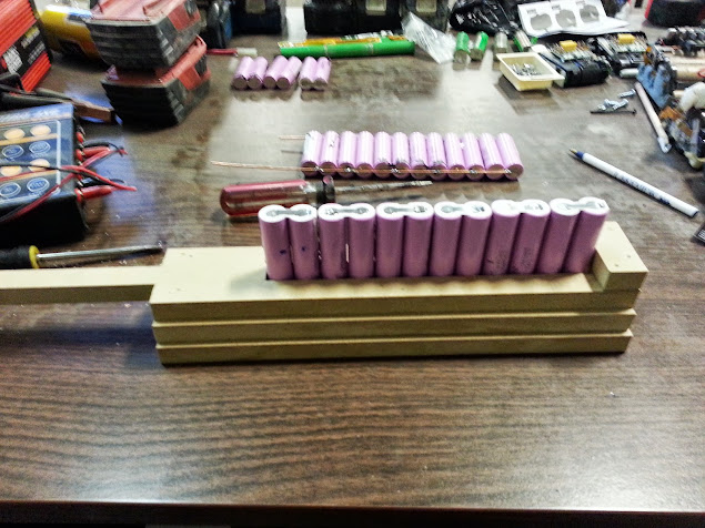
I, for 18650 Li-ion cells ...
Initial bulk charge,
separate ... into pairs,
self-bleed down observation,
then rebuild as 3s2p for inverter drain test.
Each pair rated by residual voltage.
Then resorted ...
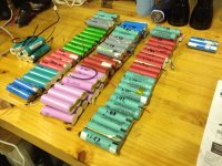
Recycled LiPo
The above "few posts up" was referencing testing a batch of Flat Lithium polymer that I'm recycling from laptop CD bay secondary batteries, 3s2p configuration.
Just got done testing and sorting the "rejects" - ones that oem laptop charger would not charge properly.
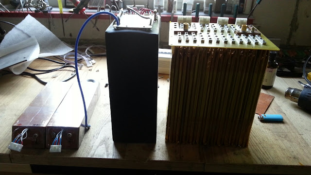
Chose 15 best for 25.9V 7s12p eZip pack rebuild.
1. Least self-discharge
2. equal cells in pack
3. Best remaining voltage after measured drain
Have another 15 for 2nd pack and lots more for "playing with" ...
large 12V pack for 110AC inverter use,
remove fuses, discharge capability tests, cordless power tool pack upgrades,
"safety testing" with over-volting, excessive drains etc.
After evaluation of testing procedure, pack performance etc. I will begin building Primo packs.
All cells matched by year of manufacture, IR, and capacity (matching retained voltage after 1 hour drain at .5c).
"Quick Test"
I did not perform any precise capacity testing, merely a reasonable comparative test.
1. Same beginning voltage
2. Timed-measured drain
3. Compared remaining voltage
Measured comparative IR, for future reference-evaluation?
Comparative IR (Internal Resistance)
I rate a comparative IR by measuring cell voltage before removing .5C drain, waiting till voltage recovers ...10min, retesting voltage then comparing.
Comparative IR varied more by year of manufacture than remaining capacity.
12.08V with a continuous .5C drain exhibited between .5V and 1V "sag"(6.4% to 12.5%).
Oh! I did build an INDEX.
Located in #1 post, with a shortcut in my signature ... below.


.jpg")


")