Spinningmagnets MAC non-hub mid drive

spinningmagnets

Moderator
Staff member
Joined
Dec 21, 2007
Messages
12,953
Location
Ft Riley, NE Kansas
MACcbs1 005.JPG

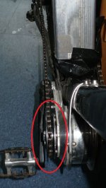
The actual drive sprocket will be a fixed 24T, I just put the 16T freewheel on to take the pic. Note the derailleur extension, because now, the stock chain is too short. I believe the MAC is the largest motor that will fit on a desirable downhill (DH) frame in this position (the Bafang-BPM is the same diameter, but slightly thinner). DH bikes are fairly strong, and they seem to consistently have the most room in this area behind the front wheel.

A while back, ES member crossbreak posted the idea that it might be possible to take a geared hub (like the popular MAC or Bafang-BPM http://endless-sphere.com/forums/viewtopic.php?f=28&t=51313), and make a modification to the internal parts so that instead of the motor-case spinning, the case would be stationary and the shaft would spin. http://endless-sphere.com/forums/viewtopic.php?f=28&t=45245. His experiments proved that this idea works, and soon there will be several bikes testing this type of system to identify its strengths and its issues.

There are several potential benefits to this, and I found it interesting enough that; I wanted to copy crossbreaks experiment myself, so...I acquired a MAC from green machine, and performed a tear-down and shaft-drive conversion. http://endless-sphere.com/forums/viewtopic.php?f=16&t=51310

waynebergman has already finished his, and he reports good performance. http://endless-sphere.com/forums/viewtopic.php?f=28&t=49467

Here, I have cut out the shape onto a 0.190" / 4.8mm thick aluminum plate with a jigsaw, and I am filing the edge smooth. Although the steel was water-jetted, the extra-thick aluminum caused MANY jigsaw blades to valiantly give their lives to finish the shape. I wanted to start out with a mount that was perhaps too strong, rather than needing to upgrade a mount that was a little too light. I also didn't mind the extra weight of aluminum, because the mount is now part of the heat-sink for the motor. Later, I can add holes (AJ?) in an interesting shape to lighten it if I can find the time.
MACcbs1 003.JPG

The BB-mount plate was water-jet cut by Big Blue Saw (0.105" / 2.6mm thick steel http://endless-sphere.com/forums/viewtopic.php?f=11&t=48811), and here I am using it to ensure proper alignment when drilling the chain tension adjustment bolt slots. The bolt slots accept 8mm or 5/16 bolts. Four on each side should be quite strong.
MACcbs1 004.JPG

I thought I might first try attaching the side-plate to the 6-hole disc brake mount. I chose this side-plate shape because I imagined that I might want to also attach a cover over the motor in the future. I may cut the future mounting-plate shape smaller if a motor-cover proves to be un-necessary.
MACcbs1 007.JPG
 
Got a 16T freewheel, which is the smallest toothcount for the common 1.375 X 24 thread, and now I also just got a 13T, which is the smallest tooth-count for the metric M30 X 1 threads. Both are from ACS and both use the same removal tool (some brands have a different tool for each size).

13T, got one from ebay vendor zxp2 ($19 +$3), and one from cycling_pros ($17.61 + $5)...make sure to specify common bicycle chain 3/32-inch (The first one I got looked right, but with very few details in the ad, I got one for 1/8-inch chain.
 
Nice work on those mounting plates, look pro ad nice and strong ;)

*Subscribed*

KiM
 
Its a converted MAC geared hub. Should be a really nice build from the looks of this so far! Nice plate work!
 
You are first one who tries to place the motor between the cranks like my last built.. this is very compact. Even a fat MAC still does not look ugly below the downtube this way. looks like you planed this well... I had too shorten my adapters and the axle/shaft. I guess you wont even need my help. Subscribed!

I'm keen to see how you'll fasten it on the down tube, screw clamps are so nice and simple, I use them for almost anything..still they always are kind of provisional ;)

Nice work on those mounting plates, look pro ad nice and strong
there is still room for enlightenment IMO :p

I like you Bottom Bracket..seems to be a prefect fit!
 
Thanks to all for the positive comments. AJ, you have been an inspiration to me with your epic builds. Everytime I am in a hurry and want to make something fast, ugly, and dirty (like my GF from high school), I remember the pics of your builds and force myself to do better.

crossbreak, my wife and I were happy before I read your posts, and now all I can think about is working on this project, so she feels neglected! I might have to ask for more night shifts at work, so I can actually get things done instead of just dreaming...

I just helped my daughter move to another apartment on the hottest day of the summer...I guess I can catch up on my sleep when I'm dead.
 
I am subscribed as well. Way to go Ron. One thought before you anchor the placement of the motor........I wonder if you could place your right crank arm on the BB spindle and spin it in one complete revolution after you get your final drive motor sprocket on the motor axle and make sure the chain does not rub on the casting of your crank arm. I know on my drive train if I have the 11 tooth running on the cassette the chain will rub slightly on the right crank arm right close to where the arm is attached to the BB spindle. In the photo you have posted here it looks like the motor may be sitting low enough for the rubbing to occur depending on the shape of your crank arm. Looking forward to seeing you getting this bike on the road.
 
I've been waiting for someone as detailed as you to show how this is done properly. Subscribed! :D
 
spinningmagnets said:
Thanks to all for the positive comments. AJ, you have been an inspiration to me with your epic builds. Everytime I am in a hurry and want to make something fast, ugly, and dirty (like my GF from high school), I remember the pics of your builds and force myself to do better.

;) cheers buddy ..i have always been of the opinion if its worth doing its worth doing well. something my father taught me at an early age, that said IMO it doesnt take anymore skill to go a little slower and get a better cleaner result
rather than hacking into it as fast as you can just to get it done...
... the satisfaction of 'doing it yourself' and getting a well functioning and visually appealing result is a great feeling!
This stuff aint 'hard' it just takes dedication and time, kudos to you for pushing the keyboard
away, pick up the tools and getting the job done! all too much 'talk' about what
one is 'gunna do' on this forum and a severe lack of acual doing...IMHO

I hope she goes as well as shes looking anyways bruv, and crossbreak haha yes
lightning holes can always be added once the brackt shape is finalised im sure teeheh
gotta have lightning holes makes shit go faster guys sheeeesh LoL

KiM
 
I thought I might first try attaching the side-plate to the 6-hole disc brake mount. I chose this side-plate shape because I imagined that I might want to also attach a cover over the motor in the future. I may cut the mount shape smaller if a motor-cover proves to be un-necessary.

Sawing a ~80mm hole into the center of the sheet, so that the 6-hole disc interface fits through saves some axial space. The motor is wider than the 68mm BB width, I'll try to keep the width between the mounts as close as possible too this in my next built (BPM2).
 
I have considered cutting a larger hole on the right side, perhaps twice the diameter of the 6-hole disc brake BCD. And then I would attach the motor-sideplate to a thinner steel sub-plate (perhaps using a 5-hole 130-BCD chainring as the hole-drilling jig?). I may still do that if chain alignment issues force it to be done (doing this would expose more of the motor shaft on the right side, and move the motors' left side inward an equal amount).

I am frustrated by how much time that unexpected issues in my personal life keep me away from finishing this. Once done, I can order several kits to sell to any interested parties to recoup the modest development costs. There is a big price break from bigbluesaw.com at 10 pieces, so I am trying to design the two sides to work using an identical shape, which would limit my risk to only needing to sell 5 kits.

Once done, and this drive has been verified to work well (see the similar drive already finished by waynebergman http://endless-sphere.com/forums/viewtopic.php?f=28&t=49467), It would be a fairly quick process to simply order more water-jetted parts, and then re-package to ship to customers. If there were no unexpected issues, a kit might be able to be delivered three weeks after being ordered. If demand was consistent enough, I could begin stocking kits for a more rapid delivery...but that evaulation is a few months away...

The input from crossbreak, greenmachine, and waynebergman has been extremely valuable...I thank you all. The BPM is slightly narrower at the stator/magnets (which is the reason for the MACs higher power potential), and it may prove to be easier to use in a BB-drive. I have yet to know if I will need crank-arms with more off-set than the common shape.

Fixed sprockets for the output shaft from the motor to the rear wheel sprockets can be easily and cheaply found with 16T-22T tooth-counts, using the ID interface of the IGH 3-tabs, or the common 1.38 X 24 freewheel threads, or Shimano cassette splines. I am hoping to avoid using an 11T sprocket for top speed on the rear gear-cluster (probably a 7-speed), but in order to use a larger set of gears in the back, I must also raise the tooth-counts on the motor-drive sprocket (if I am to maintain the same ratio).

In order to reduce the tooth-loading on the rear sprockets, I hope to use a 15T-34T 7-speed sprocket set. These seem to be the largest that are easily available at reasonable prices (for replacement when worn). jateureka posted that 24T and 26T sprockets are now available using the IGH 3-tab bore interface (http://bikesmithdesign.com/cogs/index.html), so I might try those first. I also like how the larger motor-sprocket (26T instead of 22T) will provide slightly more chain clearance from the crank-arms.
 
Even with an 18T output sprocket I got no problems with with the crank arm. With this long chain I suggest using a downhill chain guide behind the BB. Without that, the chain is likely to come of during offroad use. Additional sideplates (see picture) on the output sprocket further reduce the risk of loosing the chain during driving.

You want to sell it as a Kit? How About paying me a license fee for having the idea for this conversion :mrgreen:
 

Attachments

  • chain guide.jpg
    chain guide.jpg
    53.1 KB · Views: 12,831
How about paying me a license fee for having the idea for this conversion?

After the development costs are paid off, I will be glad to share any future profits from converted gear-motor kits from me!

I have a full-time job, so any sales will be from part-time efforts. And to be frank, I would be more eager to dive in right away with high production (the hardest work will be done by a water-jetter), if...I didn't think someone in China would copy it (they will).

But, until then...perhaps you and I will make a few Dollars/Euros? Would you like to be the kit dealer for Europe? Shipping is very expensive from USA, maybe I can just send you the drawings, and you could water-jet the metal sheets for the mounting brackets there in Germany?
 
Thx, already made my own designs...The chines already copied the idea, just look at the GNG V2 :D It's just a small step to the "dual freewheel Jackshaft" design. If I wanted to make real profit, I wouldn't have posted my idea ;) Maybe I sell some kits in the next months based on the BPM just to get some reputation. I like your idea of making things inter changeable. I will sell my BPM kits with the V5 sprocket adapter for example, maybe you could use a similar one, if you dont go that route with an own shaft. I wish you good luck with your plans!
 
I've been following the geared hub motor conversions and plan to do a similar setup on my Versus DH frame once my new CNC build gets completed. Thanks for the posts, this really helped determine the direction of my latest build, originally I was going to keep the motor intact. This is a much better approach.
 
Cross break
" just look at the GNG V2 :D It's just a small step to the "dual freewheel Jackshaft" design"

What is the advantages /disadvantages of the GNG V2 design vs the dual freewheel jackshaft design ?

I think the GNG design has one advantage that their is less drag when peddling with no motor power as you don't have to turn the motor shaft ?

How much is this friction load peddling the motor shaft ?
 
jk1 said:
Cross break
" just look at the GNG V2 :D It's just a small step to the "dual freewheel Jackshaft" design"

What is the advantages /disadvantages of the GNG V2 design vs the dual freewheel jackshaft design ?

I think the GNG design has one advantage that their is less drag when peddling with no motor power as you don't have to turn the motor shaft ?

How much is this friction load peddling the motor shaft ?

Should be the combined friction of the 2 freewheels as I understand it
 
jk1 said:
Cross break
" just look at the GNG V2 :D It's just a small step to the "dual freewheel Jackshaft" design"

What is the advantages /disadvantages of the GNG V2 design vs the dual freewheel jackshaft design ?

I think the GNG design has one advantage that their is less drag when peddling with no motor power as you don't have to turn the motor shaft ?

How much is this friction load peddling the motor shaft ?


The GNGs do not have less drag, since you have an additional chain to move there! The GNG could in theory have a little less drag if it was using "DUAL freewheel Cranks". But it doesn't ;)


cal3thousand said:
Should be the combined friction of the 2 freewheels as I understand it

No of course not. As you put power through one of them, one is engaged and one runs free (the one in the motor) if you pedal only. Also refer to http://endless-sphere.com/w/index.php/EBike_Motors_Middrive#Jackshaft_Dual_Freewheel_Config Drag is about the same that you feel if you use an IGH. If you are no time trial rider, it's negligible. You just cant feel the difference.

The GNGs are WORSE for pedaling only, since you can always hear the annoying clicking noise from the motor freewheel. Your converted Hubs use roller freewheels that dont make ANY noise when pedaling only.
 
Is it just the 2 freewheels ? because I thought that was the case for the GNGv2, but for the dual freewheel Jackshaft" design you also have the motor shaft and the 2 bearings of the motor drag?

Spinning magnets, that's what I was thinking also, that this design is not good for people who want to peddle often if their is too much extra drag turning the motor shaft. For short distances this won't make much difference I think, but if you want to go large distances you have to peddle a lot and conserve energy sometimes by having the motor off and only peddling.

Having the motor on uses a certain amount of power even on minimum power , so if you cannot peddle easily without motor power then the range will be significantly reduced . So this setup may not be suited to long range ride distances if that is the case that their is extra drag on peddling effort with no motor power ?
 
To figure out what the drag is for both scenarios under peddle only, we need to know what is turning inside the MAC motor when peddling it and no motor power ? is just the shaft or also the rotor/stator of the motor ? Also their is 1 extra chain drag on the left side of the bike which is under load when peddling, so it will have more drag then the GNG chain drag of the 2nd chain as that is not under load when peddling.

For the GNG the drag is one freewheel backwards and friction and mass of moving the unloaded chain around it . But the advantage is the power is passed direct from the peddle cranks to rear cluster, so its a more direct path.
 
For the GNG the drag is one freewheel backwards and friction and mass of moving the unloaded chain around it . But the advantage is the power is passed direct from the peddle cranks to rear cluster, so its a more direct path.

This is true. But still, you just cannot feel it since the drag is so little. As said, an IGH wastes more energy and they are still great for long distances. Just try it and you will be convinced, that it is the better solution for long distances, due that fact that you can use your motor power more efficiently, since its a more direct path to rear cluster. Most riders pedal less than 50% of the used power, so it makes sense to allocate the more direct part to the motor.

Of course the motor gears do not turn while pedaling only, due the motor freewheel. read http://endless-sphere.com/w/index.php/EBike_Motors_Middrive#Jackshaft_Dual_Freewheel_Config and you'll get how it works. We described it as good as we could, if there is anything you do not understand, let me know, then we can change the article.

For a chain, it does not matter if it is loaded or not, the drag stays the same. Only for bearing drag increases when they are loaded. In fact, the only additional drag you see for the dual Jackshaft drive is induced by the Jackshaft bearings themselves, which is negligible.
 
I think it's an important point that you maximise the efficiency when peddle ONLY and not for the motor power only. The drag of 2 extra bearings doesn't sound like much, but it will add up to a lot over long distances, as that effictively doubles the bearings in the drivetrain compared to a normal 2 bearing bottom bracket for peddle only. Maybe you can measure how much the extra drag is somehow to compare?

Humans can peddle a lot longer then any battery to go long distances. But if you have a lot of drag when peddling the bike , it will then only be suited to short distances, as you will have to use the motor more often then you like as its not easy to peddle only.

Even expensive bikes with bosch middrives suffer this problem of excessive drag on peddle only as o00scorpion00o just commented here:

http://endless-sphere.com/forums/viewtopic.php?f=28&t=51876

"Re: Haibike EQ Trekking, Bosch drive.

by o00scorpion00o » Sun Jul 21, 2013 2:02 pm

Ok I've definitely concluded there is a big drag on the bike, I don't know if its the motor or them3 speed Sram hub but its too hard to pedal for long unassisted, it reminds me of direct drive drag.

I've found myself having to use the motor much more than I like, I guess the bike was designed thinking people that want an electric bike would be using the motor a lot anyway and wouldn't notice."
 
Gab, I have an ultra-light 1,000W friction-drive that I can't even feel when it's off and I am pedaling.

This new configuration is pretty much an electric off-road light-weight 3-HP dirt bike (2,200W?). It happens to have pedals, but...it's an electric vehicle that can climb very steep uphills using 48V while not getting hot, and still able to do 30-MPH on the flats. It can do this until you run out of battery without overheating. If you swap in new batteries, it can do it all day long.

It's what I want to add to my life right now (I even still have a bicycle with no electric power), but I certainly understand if your particular commute is better served by a different kit.

edit: Due to the internal freewheel in the MAC clutch, there is no motor-cogging when the power is off and I am operating as a pedal-only. The motor-shaft simply becomes a jackshaft. But,...I don't plan on pedaling much when I take this bike out.

edit: here a video from waynebergman using the same set-up and the exact same shaft-drive converted MAC, only 1:35 long and well worth it:

[youtube]1HGr7bAl2V8[/youtube]
 
Back
Top