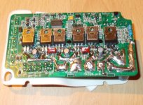
GM "Magic" controllers

I believe these are the same controllers used in the magic pie V2s. I have one here that I've been meaning to crack open and replace the caps with higher voltage ones. I'm hoping to retain the existing controller and run it on 18S lipo. Should give it a nice boost in speed while retaining everything else in a neat, sealed unit. Failing a reworked 6 fet 4110 controller running 24S would give nice performance for a low key, minimal wiring mess commuter.
 
Hyena, you will have a job switching in bigger caps rated for above 63v They wont fit the case. I searched the farnell catalog to no avail but im sure that a current mod with better fets is the way to go with these.

EDIT: doh just understood that this wont be in a case as its either in the hub or in a custom case anyway. in which case, yeah great shout Hyena
 
Regarding fitting high voltage caps, I wonder if it would be acceptable to use a smaller capacity cap, but of lower ESR and general high quality?
 
great_success.png


Traces reinforced, wire soldered to half of shunt. I undershot the 50A target a little, now running at 45A. I did a kinda stress test on a 1/4 miles steep hill, standing start, no pedalling, full throttle and controller case barely got warm. I'll have to wait for the summer to do a real test, like going through tall dense grass - full throttle at constant 5mph.
 
Great stuff punxor did you take any photos of your modding? would be good to see.
 
Sorry, I don't have any photos (all sealed up on the bike now). Not that there was really much to see.

I've been riding the bike more and it's holding up ok. It will just about do a burnout under its own weight (30kg) on dry tarmac. This doesn't seem to upset the controller.

Trouble is, now I want to double the current again :wink:

Not on this controller, though.
 
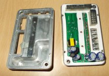
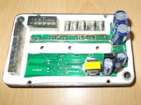
I opened up the controller again so took some photos of the first mods. This ran 47A peak according to the Turnigy 130A wattmeter.

As you can see it's pretty cramped in there. All I really did was add a little solder here and there and soldered a piece of solid copper wire to the half the side of the shunt (next the big electrolytic capacitor).

controller_original_mods1.jpg


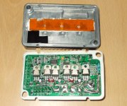
Showing clearance between the copper fet connecting rail and the case:

View attachment 4


controller_original_mods3.jpg


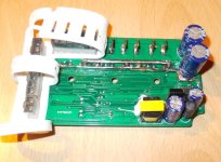
Then I replaced the FETs with IRF3077's (as recommended here: http://endless-sphere.com/forums/viewtopic.php?f=2&t=51598&p=763637). And did a little more beefing up with solder and copper wire. Main thing was to double up the fet connecting rail and the wire already on the trace.

With around 3/4 of the shunt now bypassed with copper wire I'm hoping for around 70A peak. The layout is just too cramped and compromised to do much more with it. Hopefully I'll get a chance reassemble and test it tomorrow.
 

Attachments

  • controller_original_mods4.jpg
    controller_original_mods4.jpg
    98.7 KB · Views: 2,072
  • controller_more_mods1.jpg
    controller_more_mods1.jpg
    79.9 KB · Views: 2,072
  • controller_more_mods2.jpg
    controller_more_mods2.jpg
    103.9 KB · Views: 2,072
Stress tested on a 10 mile run with a few burnouts. Peaking at 69.x amps (3200W). It's actually running a tad cooler than with the old FETs under repeated acceleration/regen. Not much above ambient, maybe 40*C or so. Bearing in mind it's currently 30*C here and this is as hot as it gets.

Lord knows what the phase amps are, but the 10awg phase wires are getting very slightly warm. So are the 3mm HXT connectors on the battery side.

Just need to increase the battery from 12S to 15S to max out the voltage capability.

We'll see how many miles it lasts...
 
Rounding this off, I bought some 3S batteries to go from 12S to 15S and it doesn't work!

The spec for this controller is 48V nominal, 60V max. With 15S connected up (60.5V measured, not fully charged), the controller makes the normal spark as the caps charged, it makes its normal faint whining noise, but no response to the throttle. Reconnect as 12S, everything works, re-reconnect at 15S, not working again. I guess it's a high-voltage cutoff, and when they say 60V max, they mean it...

It's a shame as 12S isn't quite a good match for this controller. It seems to have a smart LVC, in that the lower the pack voltage goes, the lower the current limit becomes. I suspect it current limits to keep input voltage at or above a LVC threshold. On 12S this means that by the time you get to 3.5-3.6 VPC (resting) the power limit is about 300W. Fortunately, I don't normally drain it this far, but in the winter when the batteries sag more it becomes more of a nuisance.

Next upgrade is 18S and an 18FET controller.
 
What about discharging the 15s pack to 3.92 v per cell to mimick 4.2v 14s pack? That way you could test before you buy ;)
 
48V with 60V HVC

The 12S pack was charged to 4.1vpc with the 3S pack at storage (3.8 vpc) for the initial test. Next time I run the bike and the 12S pack is at a lower voltage I'll try it again for interest's sake. 15S was only meant to be a bit of temporary fun, the conversion to 14S would be more trouble than it's worth, better to just go big(ger) :)
 
surely not too much trouble, I have a thunder power 1430 and used to own a hyperion 1420, that's why im interested in 14s and these controllers. Still mine have blown in the past so pushing the envelope on them for me is maybe not so smart. keep us posted on the max hvc if you find it.
 
Ah that's 4.09 per cell at 14s perfect, just charge with lilo setting. Thanks Punxor
 
Apologies for resurecting an old thread, but looking for info on these GM BAC "Magic" / cruise , controllers
Anyone still running these controllers ?
I believe they are programable via USB to the 12 pin socket for 24/36/48 volts, 10-50 amps , ??
..anyone know the pin outs ? ..any special software needed ?
 
Back
Top