Ebike Battery Monitoring and Control System

As Alan mentioned, only does monitoring (voltage and temp).

I'll have to look later at the PFDs posted,looking promising. The protocol I implemented is this:

wu5s.jpg


b0 & b1 define the 0 and 1 times (thus clock synchronizes here), P is parity and S is stop. I'll probably have to add one extra "parity" bit.
I'm not worried at clock variations. The synch is done on every message, so as long as the clock in the transmitter and receiver doesn't change much in a ~1ms window, it's ok. This does, however, take up a nice chunk of the available code space on the micro.
 
Thanks for the info. I'll review it. I'm thinking about making software that can recalibrate the clock via the serial in-situ anytime the error rate kicks up. Optimize it for the current temperature and voltage. The trigger for the recalibration cycle will be 2-3 bits so it will work even when the calibration is way off.

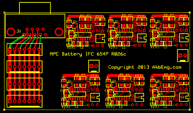
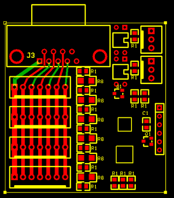
I adjusted the board to 6S4P and it is under 2" by 4". So it fits along a pack or at the end of 2 or more packs. This takes a lot less wiring than the remote monitoring/balancing I'm doing now, just 4 conductors to the master board, daisy chained through the boards. Love to reduce that wiring!

Still tuning the board for the SOIC, need to re-check everything twice. Maybe more.
 
Not meaning to confuse the issues further, I've just come across this analog front-end chip from Intersil: http://www.intersil.com/en/products...ement/cell-balancing-and-safety/ISL94208.html

I has a level shifter, analog mux, and built 200 mA FET cell balancers for up to 6 cells in a 32 pin QFN package. Standby current of 1uA max.

With this you'd only need a micro with one analog input and I2C pins to connect to it. Mouser says US$3.66 in qty 1 and $2.51 in qty 100.

You'd essentially have a 2 chip solution for 5 or 6 cell BMS. Pretty attractive...
 
2moto said:
Not meaning to confuse the issues further, I've just come across this analog front-end chip from Intersil: http://www.intersil.com/en/products...ement/cell-balancing-and-safety/ISL94208.html

I has a level shifter, analog mux, and built 200 mA FET cell balancers for up to 6 cells in a 32 pin QFN package. Standby current of 1uA max.

With this you'd only need a micro with one analog input and I2C pins to connect to it. Mouser says US$3.66 in qty 1 and $2.51 in qty 100.

You'd essentially have a 2 chip solution for 5 or 6 cell BMS. Pretty attractive...

That is interesting. Always pays to look around.
 
I like how this Intersil chip just does the part of the job that the micro can't easily do. No attempt to "do everything" and make the chip complicated (and the documentation massive), just do the part to enable the micro. Price is good. Availability is iffy, not many in stock anywhere. Tempting to buy a few, but then they might be unobtanium when you wanted them. That's one problem with these special parts.
 
Yes, I think you interpreted that exactly right. Availability, especially longer term, is always a worry with these special purpose chips. Hard to beat the function versus cost, though.

The analog accuracy is not stellar. Maximum error is 30mV on a signal of 2.1V for a fully charged LiPo, as it halves the cell voltage. So, if you use a 3.3V micro with the common 10 bit resolution, you'd only get about 650 bits, unless you use a external ADC reference, i.e. 3.3 mV resolution. I suppose you could calibrate each cell voltage input but that would tedious and expensive. I could find no spec on accuracy drift due to temperature.

Just ordered a couple of sample, anyway. Might rig up a bread board and do some basic testing.
 
Intersil has some other chips also, including the ISL94212, which was briefly mentioned in another thread here. It appears to be more complicated, you have to sign up just to get a datasheet which is annoying. It also costs about four times as much but does handle 12S and is extensible with a simple 2 conductor capacitively coupled cable.
 
Some folks are determined to balance to a couple millivolts, but the real important thing is to prevent significant overcharging, so 30mV worst case, and 4mV typical accuracy is probably fine. It would not be too hard to calibrate better, calibration of the micro's ADC is required anyway. So I would plan on that.

That data sheet is pretty brief, wonder if they have more. Probably another sign up to get more info deal.
 
Reduction of wiring is definitely high on my agenda, and I think you're right about not needing to balance to the last millivolt, so to speak. Nice layout, btw. Strange, it didn't ask me to sign up on the Intersil site to download anything. I did have to sign up to get a couple free samples, which I'd expect. The 94212 is too complex for what I want. It's the analog front end that's the tricky bit and the 94208 would address is nicely. I'll have a play with it once I get the samples.
 
Njay said:
Niice. What's the TH component on the bottom right, an opto?

Yes, the body shape on the library part isn't quite right but the hole pattern is okay. It needs another step and repeat, one of the patterns is refined and the other five were stepped already so they are an earlier version.


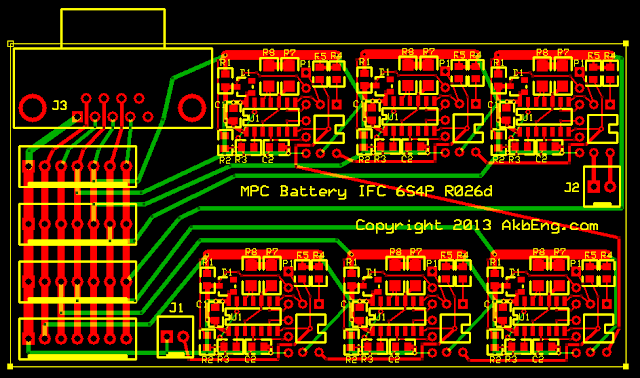
Here is the result after stepping and laying in the connecting traces. It needs a thorough checking, but it should be close to complete. It could be tightened vertically by a few mm.

Battery%2520Interface%2520R026d.png


This version has the series connected optical isolation, so each stage feeds the next, and the two pin connectors feed into the first and out of the last. Some type of clock sync or calibration may be needed as there is no resonator. Cost of parts per cell is under a dollar and a half since it uses the lower cost SOIC version of the ATTiny44. The P1 column of through hole pads are the programming pads, no jack needed just use a pogo pin programmer adapter like the one from Sparkfun (except pogo pins in one row instead of the 2x3 array), hold it against the pads to program the chip.

There's extra space on this pc board (below what is shown above) so perhaps I'll put a programmer adapter on there (and mill it off after fab). :D
 
Intersil ISL94208

This chip was mentioned above, and it looks interesting. So how big would a 6S4P board made with this chip be?

I'll probably do a rough layout to see, but it is likely that it could fit into 2x2 inches, or half the size of the above board. :D

The parts count would be about half. This reduces assembly cost.

The per cell cost would also be lower, probably less than a dollar per cell (just for parts costs). The smaller circuit board would cut PCB costs as well.

It would require soldering a QFN package for the Intersil chip. These have pins and a pad under the chip, they must be soldered with hot air or similar soldering setup.

It could possibly be made directly Arduino compatible, so just add an Arduino master and a few of the Battery Interface boards, and you have BMS Hardware!

Might be worth trying. :D
 
I've already re-done the layout of my design, just to see the effects. And, the difference is indeed staggering. Parts count is one fifth, for my 5S or 6S design, the hardware cost (excluding PCB) is less than $6. I've posted a few questions to Intersil, so will be interesting how they respond.
 
I think I've pretty much decided to give this chip a thorough testing. If it lives up to its billing, I might well switch. It solves quite a few problems:
- standby current (< 10 uA)
- level shifting for cell voltage measurement
- cell balancing (though limited to 200mA)
- minimal microcontroller requirement
- low parts count
- low overall cost
 
2moto said:
I think I've pretty much decided to give this chip a thorough testing. If it lives up to its billing, I might well switch. It solves quite a few problems:
- standby current (< 10 uA)
- level shifting for cell voltage measurement
- cell balancing (though limited to 200mA)
- minimal microcontroller requirement
- low parts count
- low overall cost

I agree.

How much balance current do you plan to use?

Which Microprocessor are you using?
 
Alan, our designs seem to converge at an alarming rate! LOL.

Planning on using as much balancing current as I can. Clearly some thermal management will be needed. The chip has a thermal pad, so hopefully that can be used to good effect. This is one of the things I want to test in an actual setup to verify the thermal model. Thermal modeling is one of the things I do in my day job. Worst case would be to use external FETs and larger resistors, which my current design uses anyway. It would be nice to have to, though, for cost reasons.

If you balance a pack during every charge, only minimal balancing is required anyway, assuming you have a good pack. The balancing history quickly identifies a duff cell and is flagged to the user.
 
Definitely shrinking!... Maybe you'll want to use this smaller opto for a little less space, don't know if the one you have is cheaper: http://pt.mouser.com/Search/ProductDetail.aspx?R=HMHA281virtualkey51210000virtualkey512-HMHA281
 
Njay said:
Definitely shrinking!... Maybe you'll want to use this smaller opto for a little less space, don't know if the one you have is cheaper: http://pt.mouser.com/Search/ProductDetail.aspx?R=HMHA281virtualkey51210000virtualkey512-HMHA281

Nice opto Njay, thanks for the suggestion.

I haven't looked too hard at optos since I have a few hundred new old stock, but that is a nice small one and the cost is fine.
 
2moto said:
Alan, our designs seem to converge at an alarming rate! LOL.

Planning on using as much balancing current as I can. Clearly some thermal management will be needed. The chip has a thermal pad, so hopefully that can be used to good effect. This is one of the things I want to test in an actual setup to verify the thermal model. Thermal modeling is one of the things I do in my day job. Worst case would be to use external FETs and larger resistors, which my current design uses anyway. It would be nice to have to, though, for cost reasons.

If you balance a pack during every charge, only minimal balancing is required anyway, assuming you have a good pack. The balancing history quickly identifies a duff cell and is flagged to the user.

Nice! Always fun to use the professional skills on a personal project. How large will the board need to be to dissipate the heat?

That's what I was thinking on balancing. Do it often and gently.

My ebike is run for about 30-45 minutes twice a day, the rest of the time it can be plugged in charging and balancing. So lets say it can be plugged in for 20 hours a day, and charging takes say 2 hours each time, that leaves more than 16 hours for balancing. If 50mA is used for balancing for a total of 800 mA Hours per day, or more than 5 amp hours per week.

So I'm thinking, make it small and minimize the heat near the batteries. If lots of balance current was needed I would want to put the balance resisters remote from the battery which is a wiring job and not so easy on an ebike.

I have hundreds of cycles on this pack, and thousands of miles commuting, and I have not balanced, just checking every few days, and it is within about 20 mV.

That's my current plan, subject to change. :D
 
Came to think about it; regarding your concerns with SPI/serial comm. Implement a checksum algorithm. This drastically increase EMI, but errors in transmission are easily dealt with.
 
Back
Top