recumbent build with homemade triple stator AF motor

Lebowski

10 MW
Joined
Jun 27, 2011
Messages
3,412
Location
beautiful Zurich, Switzerland
time to build something again :D

Over the winter I build a 2 kW triple stator axial flux motor for my recumbent. The goal is a bike where the motor
goes through the transmission so that it will climb the hills around here (which can be up to 15% incline).

The original idea was something like this:
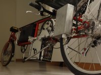
DSC01283.jpg
DSC01287.jpg
but the motor hit my legs :cry: So: new idea and how it'll be (still has 9 to 10 cm of groundclearance):
DSC01289.jpg
The idea is that you can either cycle, run on the motor alone or both. Both the motor and the jackshaft are based on a Deore rear wheel bike
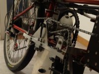
axle with a freewheel. From the motor (12T sprocket on the freewheel) the chain will go to the jackshaft (52T sprocket fixed to hub).
A steel 22T sprocket (also fixed to the hub of the jackshaft) will then go with a chain to the rear, where a derailleur will provide 7 or 8 ratio's.
From the pedal (55T) a chain will go to a sprocket (about 22T) on the freewheel part of the jackshaft.
As far as rpm's go: with 90rpm at the pedals the jackshaft will rotate at 225 rpms and the motor at 975 rpms.

From above:
DSC01290.jpg

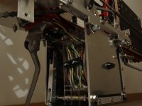
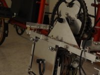
I typically build quite rudimentary as I'm lacking in the skills departement. Also, I build in my spare bedroom so I cannot weld or anything.
I'll use lots of 15x15 mm aluminium square tubing (2mm wall thickness), lots of 6mm thread which can be bent to make U-bolts, and
flat 3mm aluminium sheet.
 
Legos and zip ties, I love it, though a lack of duct tape is disappointing. I can wait for video of rides in the Alps. :mrgreen:
 
I'm amazed and impressed what you can do with basic tools and materials!
(My own attempts tend to have +-0.5mm error and assembled results end up distorted :(

I have a recumbent with a similar jackshaft and chainring setup under the seat. One problem I have is that the jackshaft flexes a bit too much when power is applied.
You mention you will put 200kg (2000N !!) on the jackshaft. With the chainrings off centre your motor and jackshaft frame might also flex. You can test this by loading and unloading either the motor or crank chain while looking at your assembly. (Easiest is to mount the chains, sitting stationary on the bike and pump the crank/pedal with a few good pushes while looking at the jackshaft and frame parts.) My guess is that a first point of weakness will be the frame corners below. Maybe stiffen with a triangular brace from 5mm aluminum?

LebRecumbent2.png

PS: If you like to see some places nearby where work=fun try visit the Micro Air Vehicle group at ETHZ or the Robotics instistute at DLR (Nearby Munchen)
 
Well it's the motors job to keep the subframe square...I hope this is enough else I will try
to bolt a flat square of aluminium to the subframe. But I plan to use my own torque (FOC) based
controller on this bike, so I'll just start with a low max torque and slowly work my way up.

Most of the accuracy comes down to the holes... I drill with a drill column and pre-punch the
hole locations with a sharp hardened nail. Then I pre-drill with a thin 2mm drill, this will
automatically center on the pre-punched impression. After that I go to the drill size required...
 
Wonderful work! to the untrained eye, this entire project might seem a bit "cluttered", but as a test mule, you are on the cutting edge of the next gen of a truly wonderful system.

FOC (AKA "sinewave") control of a brushless motor is smoother, more efficient, and most importantly, quieter than the common square-wave controller.

Giving the motor some gears? this provides a wider range of performance from smaller and more affordable motors. By shifting gears and keeping the motor in the efficient motor-RPM range, you produce less heat in the first place, and...shedding heat is less of an issue.

As to it being axial-flux (instead of the common radial flux), it allows a modular motor design. A single stator/rotor pair is light and affordable, a triple stator/dual rotor is slightly wider, but can take triple the amps, while using the same assembly-line parts!. A quad-stator/triple rotor (again using more of the same parts), can accept even more amps.

Need a different kV? swap-in different stators, no rewind necessary. The widest possible version could be mounted just in front of the rear wheel of a longtail cargobike.

The fact you are developing this on a more efficient and more comfortable recumbent shows that you are a free-thinking radical, and...if you end up adding a front fairing with an aero tail-sock...I'm afraid I will simply have to throw my hand up and walk away...

The public is not ready to accept this kind of advanced "common sense" design...
 
just made the first test ride

bloody hell !

:mrgreen:

Everything held together fine, no problem with the subframe twisting or the gearwheels sheering of the jackshaft.
Top speed was, well, fast, will put a speedo on it to have a measurement. It pulled up a 13% slope without any
pedalling no problem, the motor ran at full speed (in first gear) so was not bogged down due to lack of torque.
And I was only at 80 V ! 100 or 120 V is gonna be so cool :mrgreen:

DSC01334.jpg
DSC01335.jpg
View attachment 1
DSC01337.jpg
 
That looks like a whole bunch of work :shock: .but dang is that sweet!
 
Congratulation for the finish :mrgreen:

Amazing work.
I know the feeling riding on a self made ebike is giving. But with a selfbuild motor + transmission + throttle it must be something in ² of it :mrgreen:

How much efficient is this form of motor ?
 
Great job. Selfmade motor and FOC controller deserves lots of respect!

the whole transmission does look very complex as well
 
Simply beautiful hand-machine work. When I used to do that kind of stuff for trike frames it looked like beavers chewed it! Great stuff!
otherDoc
 
After going up and down the neighbourhood all day yesterday I finished testing of my recumbent and took it back
inside for the winter (there'll be snow at the end of the week, but I don't care as I'll leave for Malorca the coming
weekend :mrgreen: ).

Speedwise it's just too fast for its own good. I didn't measure speed but at a certain point you can feel that the
frame start weaving a bit, it starts to oscillate slightly. But I think this is unavoidable seeing as that the bike
is basically a big ladder on its side. The more than 2000W on the street (so after elec. losses) is very nice, I
don't even need the lowest gear to go up a 13% slope :D Basically it has nothing to do with a bicycle anymore,
to me it feels like a souped up moped. Especially when you start racing cars from the lights, going up a 5% slope :D

Things I will change over the winter:
- tacho with speed limiting function (for safety but also legal reasons). Bought me a nice (single color) 128x32 OLED display
and will build a tacho mimicing the one from an old Citroen car (which has a tacho with a fixed need and a drum with
numbers rotating behind it)
- build a new 6 FET (150V 32A phase) controller, use proper 50A current sensors and not the 150A from the test controller
(and have proper power at startup (sensorless) by using high frequency signal injection to measure magnet positions)
- make a cover for the battery department
- change to a rotary grip shifter on the left handlebars
 
busy with the last metalwork and other things before I start building the controller.

I made a battery bag with a wooden backplate for carrying 30s LiPo:
DSC01390.jpg
the bag is made from 1mm thick PVC sheeting, sold here for the purpose of lining the garden
pond (I still have a few square meters of the stuff as I used it for lining my folding kayak). The
stuff ir very easy to glue.
DSC01391.jpg
Big zipper sewn in with the sowing machine:
DSC01392.jpg
one 5s brick:
View attachment 6
for the controller:carrier for the 6 FETs with holes for the phase wires and threads for mounting
DSC01396.jpg
some cooling fins (only 3 to 3.5 kW controller):
DSC01397.jpg
the controller is in a 1550G box from Hammond, as sold by Digikey. Here the lid is mounted to the rear fork of the recumbent:
DSC01398.jpg
View attachment 2
how it will be sitting, wiring and throttle cable coming from underneath:
DSC01401.jpg
already got the PCB, still have to order parts !
DSC01403.jpg
 
basically finished :D build time about 16 months
 

Attachments

  • DSC01499.jpg
    DSC01499.jpg
    66.5 KB · Views: 4,737
  • DSC01501.jpg
    DSC01501.jpg
    70 KB · Views: 4,739
  • DSC01504.jpg
    DSC01504.jpg
    55.2 KB · Views: 4,736
  • DSC01506.jpg
    DSC01506.jpg
    53 KB · Views: 4,737
  • DSC01491.jpg
    DSC01491.jpg
    93.9 KB · Views: 4,741
Awesome!! :D :D
Thanks for the link bud!
A video of you ripping in the street will be so cool! Please :mrgreen:
The 500W loss, how does that compare to other motors from the shelf? That means you have 82% +- efficiency?
 
Back
Top