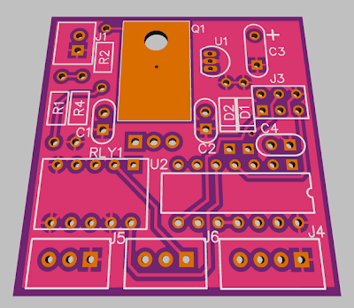
RFID Keyswitch PCB Version 0.1
Here is the new version, slimmed down, simplified, all through-hole, and with linear regulation. KISS = Keep It Sweet and Simple.
Board is about 1.5 by 1.6 inches, and 2.4 square inches.
J1 is power in from Run/Kill switch at full battery voltage (only on when running)
J3 is programming jack, used to load software into the micro, just pads (no actual connector)
J4 is RFID receiver, 5V up to 40 mA, Wiegand or Serial/UART
J5 is Power Out (when unlocked) to Main Switch Board, or power the controller (logic only), up to 200 mA at battery voltage
J6 is dry relay contacts SPDT (no power, etc, just direct to the second set of contacts on the relay)
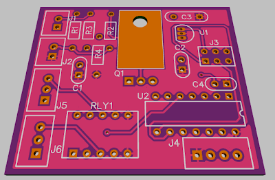
Pre-Regulator is TO220 FET type selected for battery voltage.
5V Regulator is low quiescent current type, 50-100 mA output, several available
Output is Relay DPDT dual coil latching type, so once the key is "open" the relay is latched and does not require power to stay there. The micro will power down and very little power will be consumed after the initial search for the RFID key.
Microprocessor is ATTiny 24/44/84 family in DIP package (2K/4K/8K flash memory size), and there are 2 unused pins on the micro at this point.
The way this will work:
1) Turn on the Run switch, this applies power to the board
2) Micro wakes up, opens relay, powers up RFID receiver and looks for keys
3) Swipe the RFID key within the time window (say 10 seconds)
4) If key is good relay closes and applies power to bike, if not it keeps listening
5) After unlocking or timing out micro shuts down RFID and itself to minimize power consumption
Power consumption when Run/Kill switch is off is zero
Power consumption when Run/Kill switch is on is high for the time window, 50 mA = 5 watts on a 100V bike (depends on RFID receiver power, may be less)
Power consumption after window (running or locked) is low, depends on a few things but should be less than 1mA, possibly a lot less

")