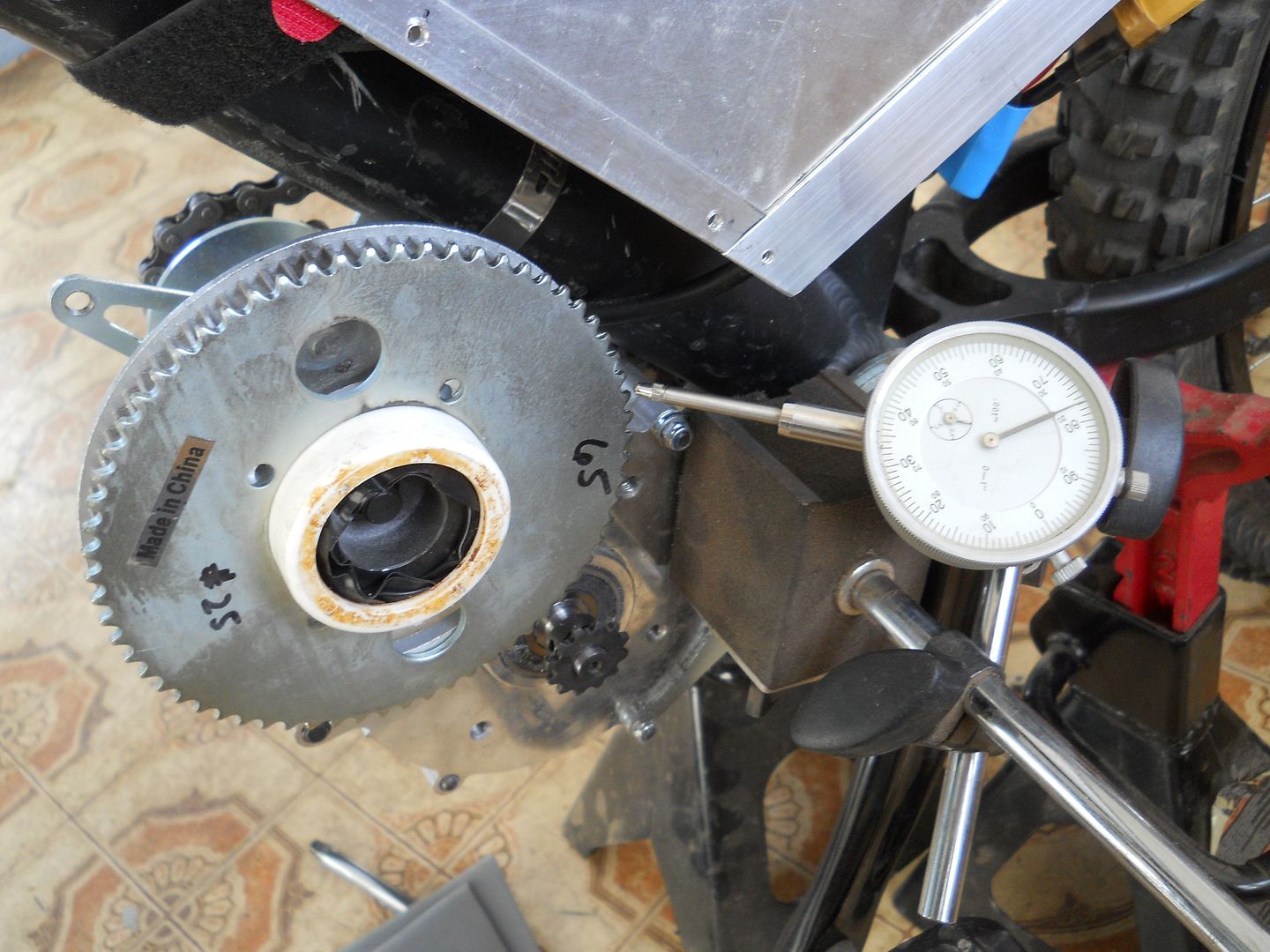
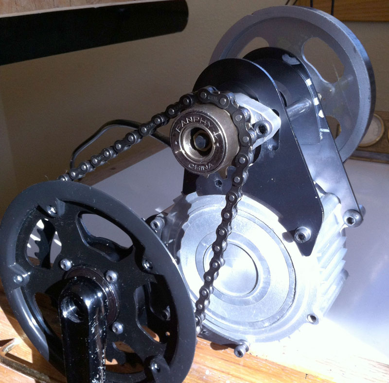
This is how I did my primary chain conversion using these parts >>the parts are from TNCscooters.com , # spk-103240 for the 65 tooth , #spk-106012 for the drive sprocket , and 2 ft of # chn-105250 chain , you will have to find another supplier for a #25 halflink , I used the original large belt pulley and trimmed the outer edge off , I then made a bushing to help center the sprocket on the pulley and kept adjust it untill I had virtualy no runout,
once I was satisfied I hotmelt glued the sprocket to the pully to keep it in place and then drilled and bolted the sprocket on,
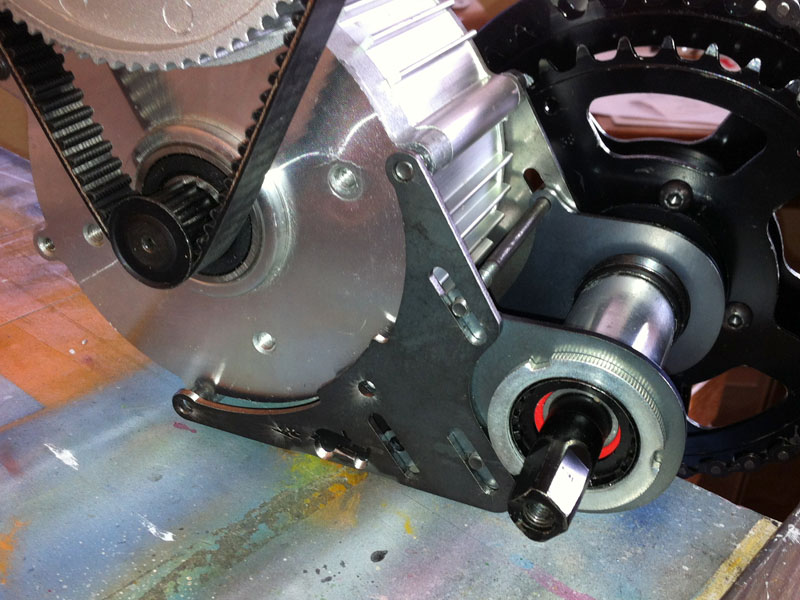
I remover the outer " washer" from the motor drive pulley simply by bending it off with pliers and used a new file with the motor turning at a relativly slow speed to turn down the pulley to 10mm, by going slow and checking my work often I ended up with a nice snug fit for the new sprocket and again zero runout, as the shaft gets smaller material is removed very fast so check often. this took less than two hours of careful work.
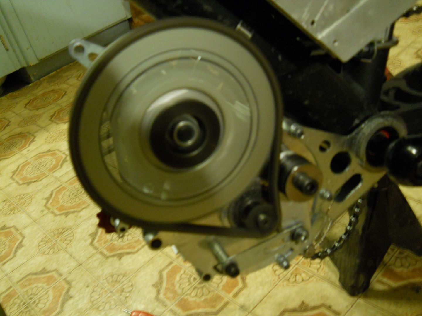
CLICK ON THE IMAGES FOR VIDEO

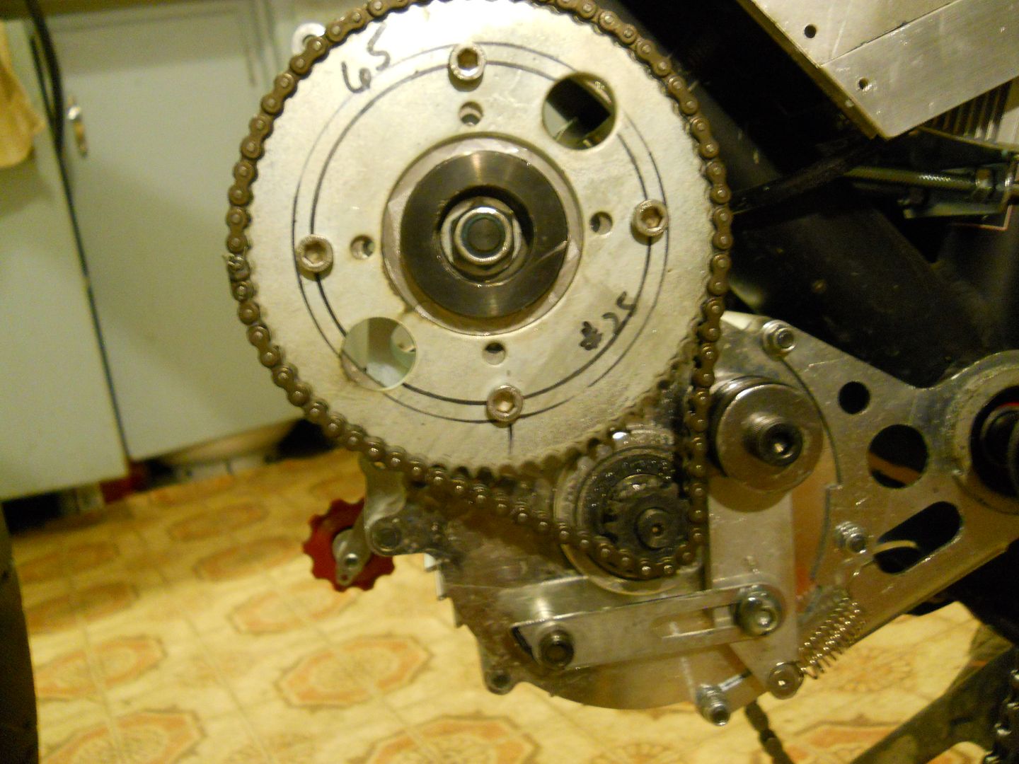
The drive sprocket had to be tapped for set screws and two flats were filed on the shaft for the setscrews to bite against once I had correct chain alignment. To have minimal slack in the chain I used a half link instead of a master link.
The result is a smooth running primary drive.
the tensioner was made from an old dirt bike chain roller cut down ,the spring from the original secondary drive tensioner which isnt needed there and scraps of aluminum.
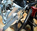
So far under hard use this has held up perfectly and is almost as quiet as the belt with the added bonus of eliminating the huge power consumption of the belt system, with " Lighningrod's adjustable sheets I hoping to do away with the tensioner and save even more power from being wasted.