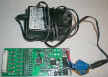
connections for? EcityP Smart S5-13 BMS

I made a slight mistake in the previous post. There is an option to enable bleeding in idle/OV condition not idle/OC as I wrote.
I enabled it last night and disconnected the charger while 1 of 10 cells was in OV condition, 1 cell was way lower than the rest.
Now the status is that 9 cells have voltages between 4.196 and 4.199 V, the low cell that was 4.147 V last night is now up 4.180V.

Obviously the OV cell has dropped below OV treshold which is set at 4.2V, but it could have dropped by itself before bleeding started.
Will try to verify this.
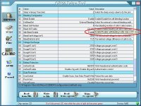
oz890_bleeding.JPG

Idle bleeding is enabled by setting bit6 in EEPROM register 2dh.

The data sheet says that bleeding is disabled if any error event is active, but the software screenshot above says enable in idle/OV.
Hopefully the data sheet is wrong on this point.
 
I have tried that option, id does bleed in idle. However it does not in OV state, so balancing takes forever. Maybe different chip revisions?... Probably it is a known bug in the chip, but it is not like we can get an errata sheet...
 
helgeo said:
I have four of these BMS'es, two 12S and two 10S. All preconfigured for LIPO voltages. Have tried one of each, the 12S is working as it should; it charges and balances. The 10S is behaving in the same way as reported by friendly1uk and Knutix.

I sent this cycling board too forum member Crossbreak in Germany. He looked at the software and found the charge level leds were set wrongly. He thought it would make no difference, but when he came to test the board it works.
 
circuit said:
Maybe different chip revisions?
I am not aware of any chip revisions made and the valid tech reference still is the "08/03/2009 OZ890 - DataSheet - V1.6":

OZ890 has embedded O2micro “Balance on Demand (BOD)” technology which starts up bleeding when the following conditions are all satisfied:
  • Battery pack is in charge state (current larger than the charge state threshold) or in idle state (current smaller than the charge state threshold and larger than the discharge state threshold) if idle bleeding is enabled by setting bit6 in EEPROM register 2dh.
  • The bleeding function is enabled
  • The highest cell voltage exceeds the bleeding start voltage
  • The cell voltages’ difference exceeds the bleeding accuracy
  • No error event, like OT, UT, OV, UV, OC, SC. If any error event happens, bleeding stops right away.

For the OV state (OV event occurs if Vcell ≥ OV threshold & delay timer expires) this behaviour is wrong since only bleeding could reduce the highest cell voltage and allow for balancing the pack.

As said above: that's a chip bug.

I could imagine / I use the following patches:
  • keep charging current < bleeding current at least towards the end of charging (I think this is the intended strategy, however, the BMS can not signal to the charger to do so)
  • keep a load_current < charging_current connected to the BMS whilst charging e.g. keep the lights on - this will reduce V_cell below the OV_release threshold and the BMS will resume balancing until OV threshold is hit again etc.
  • allow for idle balancing and stop charging before reaching OV by adjusting the CC/CV limit of the charger.
 
See if this is palatable...
If someone screws up during assembly and sticks a killer voltage in, you don't want it to try and bleed it down, it will burn the board.
OV is a fault condition. It shouldn't happen. The charger should be cut off while the cells are still within the balance zone. Which unlike other boards is not only at 4.2v+ so we don't need it to keep operating way beyond this point.

Edit: Remember, it is not there to fix problems. It is protection and preventative maintenance. If a pack goes wayward enough that a cell is getting so far ahead, then trying to cover the problem is not the boards job. The end user is expected to know nothing, but will notice their range has decreased. Time for a new pack anyway. Trying to carry on is flogging a dead and potentially dangerous horse
 
friendly1uk, incorrect.

With modern cells, only like 0.5% difference in SOC will lead to high difference in voltage at the end of charge. For example if you have 10 pcs. A123 cells.. One could be in 100% SOC and the rest at 99.5% SOC.. Which translates to one being at 3.65V and others at, say, 3.55V. For this pack we need to set the charger to 36.5V. So, 9 cells x 3.55V + 1 cell x 3.65V = 35.6V, which means that the cell with 100% SOC will be able to go up to 4.55V...
Mind you that 0.5% difference in SOC can appear in perfectly assembled and absolutely new pack, due to temperature difference in the center and outside the pack, for example.
So even with 0.5% difference in SOC, OZ890 will show an OV error and will not do anything about it. Over time, this difference will grow and range will get smaller, even if the cells are in perfect condition.

So yes, it is a bug in the chip. Or it is designed this way due to manufacturer's lack of understanding. This is not a new issue, even Linear Technology arrogantly says "we know everything there is to know about batteries" (insider information) when clearly they don't. Even cell manufacturers don't know much about their product.
 
It sounds like your gripe is with the balancing currant. The thing that should stop the fault occurring.

This board has fail safes. Points at which it admits defeat and quits. OV is one of them. It is past all the 'time to do something' thresholds so now it is time to stop because it is out of control.

Having spoke to a few industry professionals I know it is a very complex subject. Besttech actually asked what an hvc was, asking if I meant the 4.28v cut off point. So things that are actually quite technical are bound to cause some confusion. I'm just playing for team 890 here based on there production volume, because a few voices on an internet forum offer no weight against the 890s achievements. I know it works. Even if people are clouding the waters.

Has this bug as you call it, actually caused any problems, or is it just theoretical. I do see your point despite taking the 890s side. On occasion I won't get to my chargers usual 50.46v (12s lipo) cut off point, but instead it will stop as low as 50.25 so this could be the OV sensing. However it is not consistent, It will come right again on the next charge. My voltmeter is also through a keyswitch that causes similar levels of voltage wander as I wiggle it. I have no fear, but it is interesting.
 
If that was the case, it would have a separate parameter at whitch the cell is connsidered fully charged, leaving current OV parameter as a panic trigger. All proper BMSes I know (ant the one my company is producing) do have separate parameters. Whithout additional parameter, it is impossible to reach "fully charged" state on all cells because it is the same level when panic starts.
 
You posted while I edited. Oops :)

Yes, perfect balancing would require things doing differently. An extra threshold as you say. Why do you want it to be perfect though. It does not matter. It gets them as close as it can during the time it is charging. Switch's off and gets unplugged. As long as it is more effective at balancing then the cells are at loosing balance it will work. If it can't keep up, the balance currant is too low. Nobody is saying that though.
 
You sound like you know what you are talking about, but... Have you tried it?
I have. I set my lab PSU to exact current and voltage. Plugged in 8s of A123 26650... And guess what... It is impossible to balance, no matter how much disbalanced the pack is, let it be 0.5% SOC or 50%... Result is the same.
 
Friendly1uk, your LED's do fit fine, simply place the anode top of its designated pad (towards the CFxx capacitors), then the other end (cathode of the LED) will end up right in front of its current limiting resistor.
Good luck!

friendly1uk said:
romelec said:
rolf_w said:
the 'bleeder' LEDs are very helpful. did you solder them manually? tricky job...
Yes, it was very easy :wink:
The leds are standard yellow in size 1206, but the PCB size is 0603...


Following this, I ordered some 1206 led's and they are way to big. You can't see the solder pads when they are placed on the board. My led's are not square at the end either, they have a D shape cut out which gives you a much better window on to the circuit board below. Still... There is nothing visible to solder too.


If anyone wants 30 1206 led's and some 470 resistors, I can do you a great deal, so I never have to see them again.
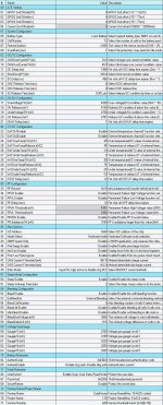
 
Finally had time and got one of these (http://endless-sphere.com/forums/viewtopic.php?f=14&t=54156) working.
ES member Schwibsi kindly lent me his I2C adapter/programmer and here is what I got (wrapping my brains around it):
SmartBMS_orig_EEPROMv.jpg
Tried to attach the mpt and eep files, wouldn't let me.

I need to limit the HVC to 4V and the cutoff to 3.65V and increase discharge to 40 A (did add a third FET), these I can do myself I think.

But what would I need to change to make it better (in regards to balance charging F.I)?
Please share your insights.
Thanks!
 
could you get the I2C connection established while just connecting 12V? mine doesn't if I do not connect any cells voltages to the balancer.

First thing I would do is to set down short circuit delay... 256µs works fine for me. If you let it as is, you could have some burned charge fet if you short cut the charge leads with 12s lipo attached.

You can just zip your files, then you can upload them
 
Hi Crossbreak,
thank you for your reply.

Yes, 12V is fine, IIRC 8.5V are minimum, didn't have that, so I used one of these 12V/1A external harddrive bricks, didn't dare to hook it up all the way to the batteries as of yet. (Am impressed with all of you who just connected this BMS right away!)
Of course the FET functions probably won't work correctly because the (internal) 12V regulator needs more, but this is just a check and see setup.

I read somewhere that one needs to short all upper cells not in use, but the minimum should be 5 cells.
So I shorted all cells up to cell 5 as needed, i.e. V13 pad (I traced those test pads on the bottom and they are the right ones) shorted with V12 ...V5. Nothing else connected.

Thanks for the hint with the zip, didn't try that, attached.

What is your recommendation with the balance/discharge, I read conflicting things and have no means to really try it out myself.

View attachment Original configuration.eep.mpt.zip
View attachment 1
CIMG7608s.jpg


Thanks!
 
crossbreak said:
... mine doesn't if I do not connect any cells voltages to the balancer...

If pin VBAT4 does not have >6.5V the OZ890 will not start! r
startup_sequence.jpg
 
Yes, 12V works fine, all the data was done with that. It works at B-, too.
Just noticed that I had the wrong 12V picture, sorry, updated.
 
I think I may have found another problem with this BMS. A couple of months ago I made a 5Ah 10S lipo pack with integrated BMS. It seemed to work well, charging and balancing was behaving as expected.

But last night I checked the pack after it had been unused for a few weeks. It was dead, no power on the output and the charger would not do anything.

I opened up the pack and checked the individual cell voltages, they were all at about 1.5 volts :shock: They were well balanced but obviously way too low. I'm pretty sure that the pack was almost fully charged before it was put away.

So the big question is, does the BMS drain the battery slowly? If so it is useless for my purpose. Anyone else had a similar experience? What to check?
 
From what I understand one way this could happen is if you turned on "Idle Bleed" as mentioned here
http://endless-sphere.com/forums/viewtopic.php?f=14&t=20971&start=125#p792853
and the "Minimal Bleed Voltage" was low.

And one of your cells (or more) was bad and thus dragged down all the others over time.

Having the standby mode off would do the same of course, but you did check that I assume.

Or some other parasitic draw.

I checked the SmartBMS and it really draws only uamps.
 
I had Idle-bleeding activated and also set minimum bleed voltage to 3.5V.
I have a suspicion that the minimum bleed voltage is ignored when idle bleeding is on. I have now tried to turn off the idle bleed and will see if the pack can hold its charge.
Will also try to enable idle bleed again and set minimum bleed voltage much higher just to see if it keeps bleeding after that threshold is reached.

Also noticed that the BMS reports quite uneven voltage between cells even if they are well balanced by an external (RC) balancer. Will try to calibrate the BMS.
 
Yes, calibration is a must, but be careful, check this here:
http://endless-sphere.com/forums/viewtopic.php?f=14&t=48461&start=75#p822934
With checkmarking the communication.

It might be that my unit got that mentioned issue after I calibrated it (again).

Calibrating seems to be a little like an iterative process and must be done with no balancing taking place.

I had to calibrate a few times but each time the actual difference was less of course.

I see in the EEPROM data that the slope and offset for the AD converter have some values, but considering bmsbattery.com quality control (or total lack thereof) I doubt that these values are real and think that they are just appling those settings to all of the boards they sell.

Hope you'll find the reason for your leak (and kindly update us here with your findings), I plan to leave mine on for weeks/month.
 
Thanks for the tip on checkmarking the communication, I noticed that saving of EEPROM data seems to take longer when it is on. Guess there might be some retries taking place?

I have now monitored my pack for about two days with idle bleed off, and it is holding its charge well.
Have now set bleed lower treshold to 4000 mA and enabled idle bleed again, will check tomorrow and see if it keeps bleeding below 4 volts.

Have not calibrated yet. Should calibration be done on fully charged pack or some other voltage? I guess it is most important that calibration is correct at full cell (4.2V)?
 
That depends on the slope and offset adjustments of the AD converter.

My guess is that these corrections did not take place with the bad products from bmsbattery.com .

I have two units with the exact same correction factors, which is statistically next to impossible.

Maybe use the middle of the range, and use a good voltmeter, and a stable and known/measured temperature, preferably at 25C.

I guess that o2micro offered some tuning software to manufacturers for the neccessary finetuning of these things.
The OZ needs to be switched to software mode to be able to accomplish all this.
 
Back
Top