
You are using an out of date browser. It may not display this or other websites correctly.
You should upgrade or use an alternative browser.
You should upgrade or use an alternative browser.
420A 24S ESC by aliens
- Thread starter bearing
- Start date
Byte
1 kW
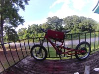
kelvinscott76 said:i have done 72mph so far on this bad boy
Which front brake are you using? Is it a bicycle brake or motorcycle?
kelvinscott76
1 W
it is a bicycle front brake 203mm (avid)Byte said:kelvinscott76 said:i have done 72mph so far on this bad boy
Which front brake are you using? Is it a bicycle brake or motorcycle?
zombiess
10 MW
kelvinscott76 said:i have done 72mph so far on this bad boy
GPS? Video proof? What KV is your motor and what voltage/amps were you running?
I am waiting on one more part from Bruno before I hook this up to my bike and give it a shot. I am building an external shunt and adding a CA DP plug to the controller as well to make life easier and to limit battery current if nothing else. This controller is quite large and dwarfs the Fliermodel "400A" controllers that others have posted links to.
hjns
100 kW
Hi Zombiess,
Can't wait to see your results with a cromotor. After breaking my frame, I am building my Big Hit with your Monster controller for my cromotor, but if this Alien thingie works as well up to 100V 150A, the smaller package will be a huge advantage. I will still keep your controller though!!
Can't wait to see your results with a cromotor. After breaking my frame, I am building my Big Hit with your Monster controller for my cromotor, but if this Alien thingie works as well up to 100V 150A, the smaller package will be a huge advantage. I will still keep your controller though!!
Cool, can't wait for your test.
zombiess said:kelvinscott76 said:i have done 72mph so far on this bad boy
GPS? Video proof? What KV is your motor and what voltage/amps were you running?
I am waiting on one more part from Bruno before I hook this up to my bike and give it a shot. I am building an external shunt and adding a CA DP plug to the controller as well to make life easier and to limit battery current if nothing else. This controller is quite large and dwarfs the Fliermodel "400A" controllers that others have posted links to.
zombiess
10 MW
I have been doing very little for several weeks due to pain, sorry guys.
sacko
10 kW
Anymore updates on these?
Once I have my Cromotor/Greyborg built up, I am tempted to go to Liverpool with the bike and get one setup and fitted.
Ideally, was hoping would test one before I had a chance to get my hands on one")
Once I have my Cromotor/Greyborg built up, I am tempted to go to Liverpool with the bike and get one setup and fitted.
Ideally, was hoping would test one before I had a chance to get my hands on one
brunotollot
100 W
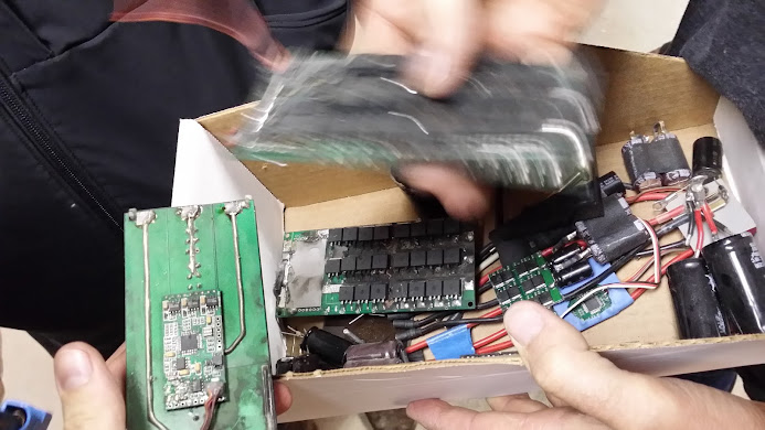
Hi Guys, quick update about the sensored system. It perform well on bench test. The motors are made by internal PCB with hall effect sensors and temperature sensor. By program software you can set the temperature cut off.
Video will be posted soon. Just few things need to be fixed.
http://www.youtube.com/watch?v=rTgkiEHaYOg
.jpg")
Video will be posted soon. Just few things need to be fixed.
http://www.youtube.com/watch?v=rTgkiEHaYOg
sacko
10 kW
Looking good Bruno
Have you tested these with a hub motor?
Have you tested these with a hub motor?
Byte
1 kW
Looks niceee
brunotollot
100 W
Byte said:Looks niceee
Many thanks.
sacko said:Looking good Bruno
Have you tested these with a hub motor?
You mean the ESC? Yes. I'll post a video soon. Just busy in too many requests and prototype. Many customers already are using them with hub motors. You can see some videos on YouTube
Regards
ls7corvete
1 W
brunotollot said:Hi Guys, quick update about the sensored system. It perform well on bench test. The motors are made by internal PCB with hall effect sensors and temperature sensor. By program software you can set the temperature cut off.
Video will be posted soon. Just few things need to be fixed.
http://www.youtube.com/watch?v=rTgkiEHaYOg
Sweet! Will these pcb motors be only the 80100 or other sizes as well?
gwhy!1
100 kW
so Im assuming that these boards are not adjustable as the hall sensors must be in the slots.. does that mean that only delta wound motors can be used with this contoller/esc combo as the timing on any motor Delta or Wye needs to be spot on to run at max power/efficiency so ideally the sensors needs to be adjustable .
sacko
10 kW
brunotollot said:You mean the ESC? Yes. I'll post a video soon. Just busy in too many requests and prototype. Many customers already are using them with hub motors. You can see some videos on YouTube
Any updates on this? I can't seem to find one..
liveforphysics
100 TW
Finally got to testing the controller. It's rough to be a low task on my priorities list. I was considering doing the test on a large dyno, but I'm batting about 0 for 4 on getting an RC ESC to survive the start-up of getting the very heavy dyno roller up to speed before they puke magic smoke, and I really wanted to see it have a fair shake at what it could do for sustaining easy to drive continuous power before that.
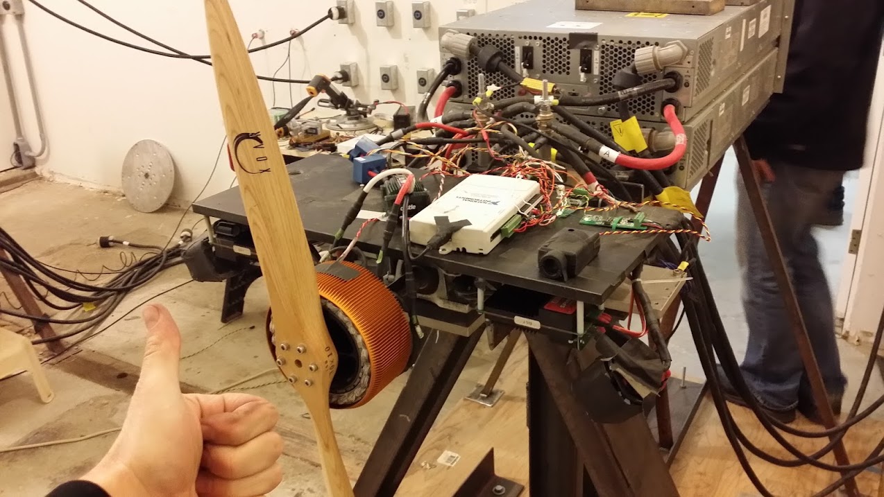
I'm fortunate to be friends with perhaps the most experienced and well equipped large scale RC motor controller testing team on the west coast. Here are a few pictures of some of the dyno-stands they were tinkering on when I arrived.
And a larger test running. Notice the big RC ESC's stuck under the front edge of the test stand.
We tried the controller on a number of different motors to find something it sync'd well with. Oddly, the larger Joby motors didn't hold sync well. For some reason the motor would occasionally buck or hicup a bit, and sometimes make a growling sound and shut down and need to be power-cycled to spin the motor again.
This was the largest outrunner I've ever got to play with. Feeling the unstoppable torque at lowest throttle setting on the large-pizza sized Joby blew it away though.
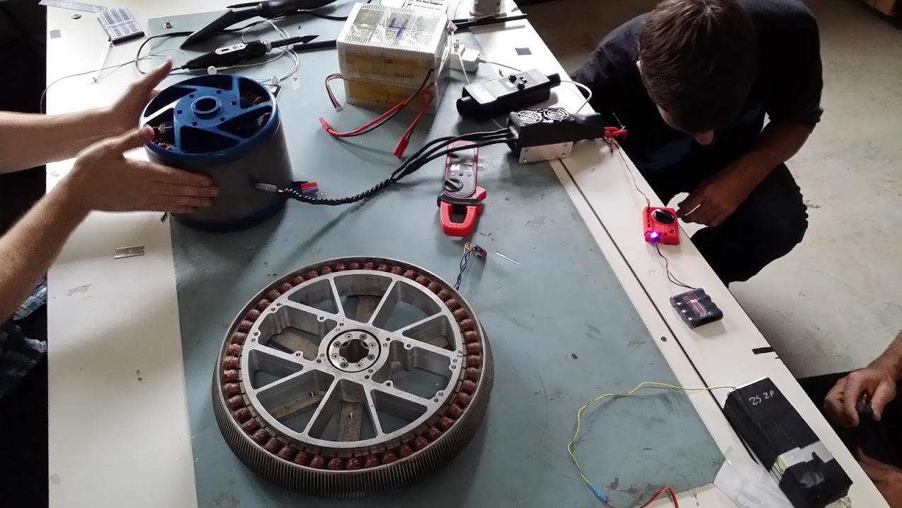
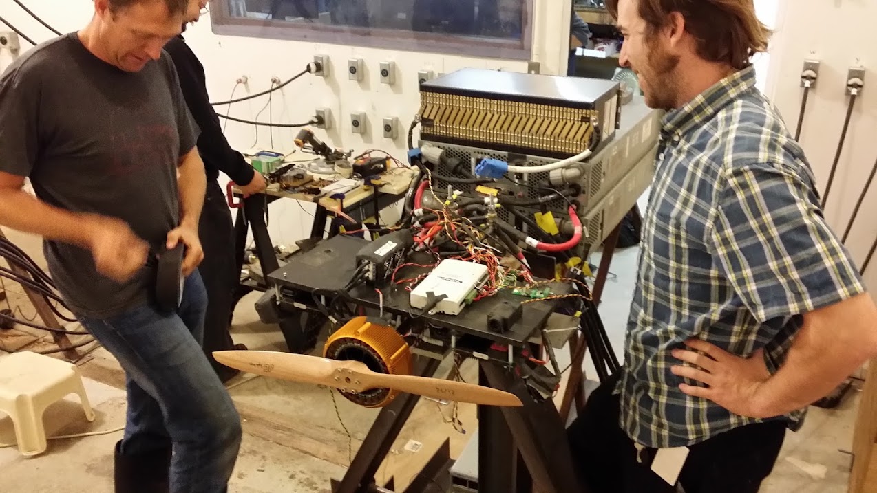
That's a room full of motor designers and motor control designing nerds. My kind of paradise.
When we found the JM1 motor was an excellent match for the controller (never lost sync, had excellent response and smooth torquey starting and relatively quiet operation (quiet for a trap controller, the motors are silent on sinus control). It also didn't show hicup'ing behavior while running the JM1, I'm not sure why.
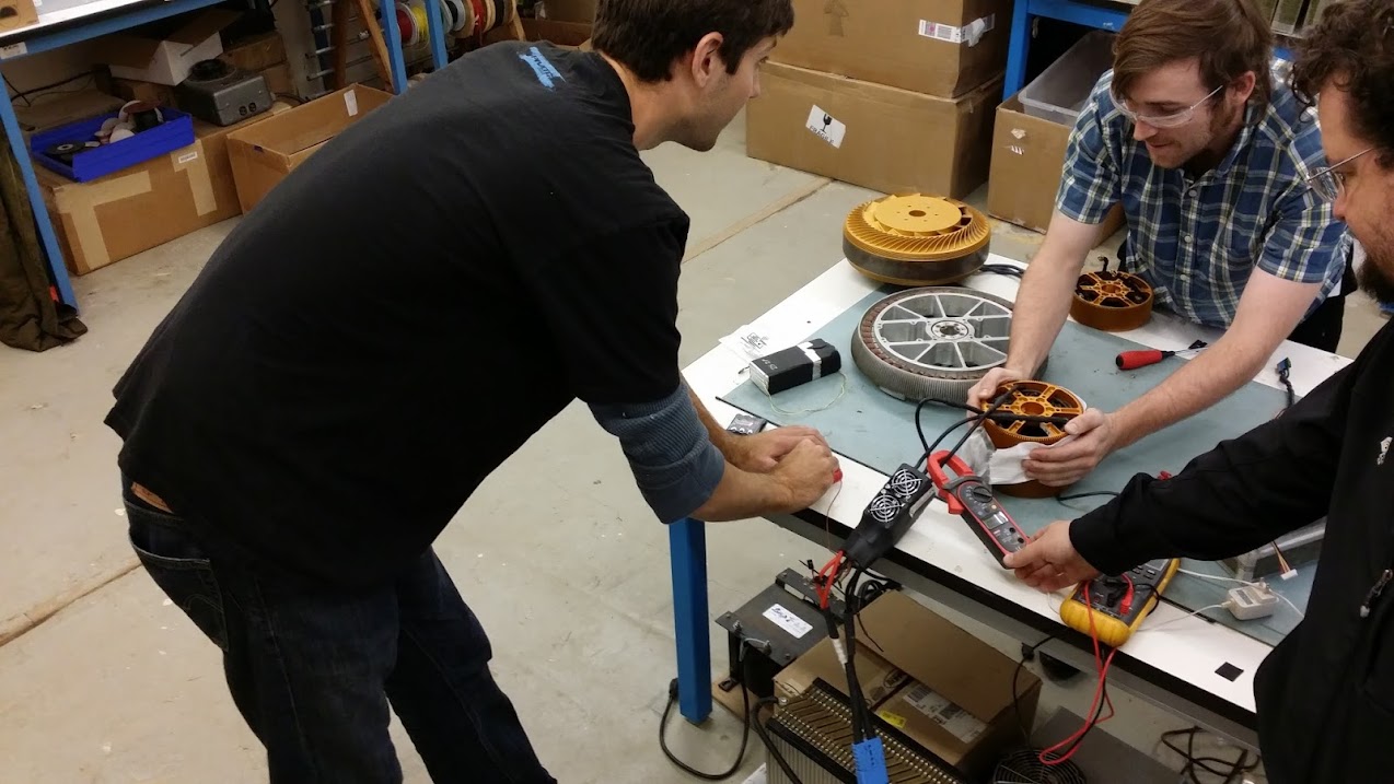
Next step was selecting the best winding option to not over-load the controller for our first round of tests. I don't recall the exact kV, but I think it was close to 60-70kV.
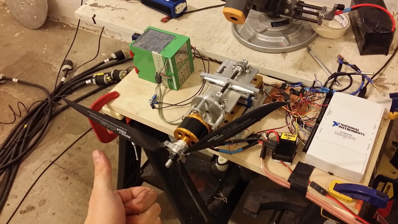
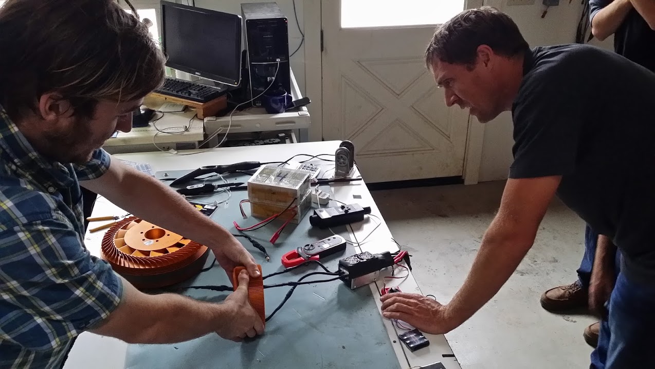
The experts selected an appropriate load prop (I am not a prop calculator wizard like these guys) and mounted it up.
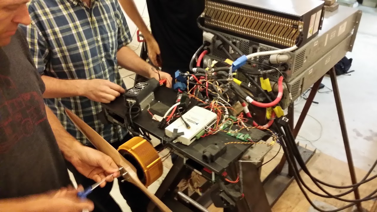
Then we mounted up the instrumentation and taped down the battery up top and taped down all the wires thoroughly, because the prop-wash from these things is like a tornado. The test stand measures not only input power to the controller, but also output power by measuring the reactive torque on the motor mount with slick strain-gauge setup and the RPM of the prop.
We did some baseline tests (sub 20amps, on a low impedance 40Ah battery at ~90V) to verify the instrumentation we wanted was working well, and that nothing was getting warm on the motor or controller (both stayed below ~35c running at 20amps, about 1800w for a minute).
Here is some video from the pre-run testing/tuning/confirming instrumentation etc.
[youtube]1OkKepn2toI[/youtube]
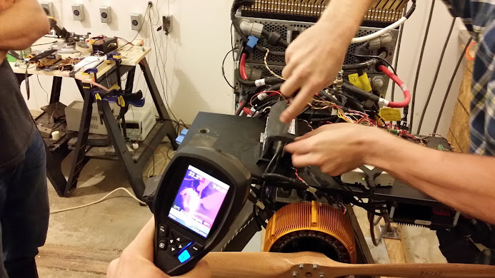
Now we start at just 30amps, then 50amps. It does fantastic. I interrupt the test early to check on it with the FLIR. It looks fairly cool from the surfaces you can see, which peak around 40degC (104F), pretty chill, and the fans were blowing slightly warm air. No issues for this power range, smooth control with no hicups or faults. We were all pleased and stoaked to see how it would do at step 2.
[youtube]LMCAB3o5Kw4[/youtube]
Then we began our second power handing test run targeting 100amps. It did do 100amps for longer than many RC controllers (you hear how excited we all were in the dyno room!), however as you can see from the plasma flashes I was lucky enough to catch on video it was not 100amp stable, though it did achieve it easily (not too many of the >12s RC ESC's can reach 100a before exploding.)
[youtube]J2ESeGcOVaw[/youtube]
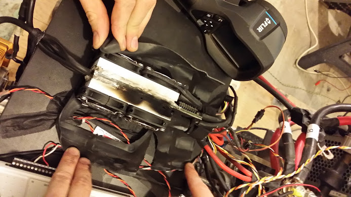
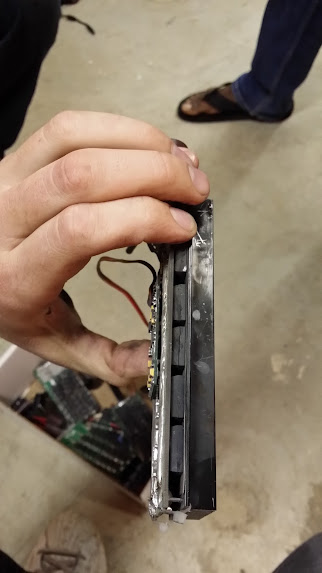
We cut the shrink to see if by chance we could see what failed. The heatsinks immediately after shooting plasma weren't up to 100c. However, the fans did a good job of rapidly cooling them to like 40c again just a minute after it blew (the fans were powered by an external power supply that stayed running).
Looks like FET smoke to me. I'm not going to be able to fix that easily to try again.
They had a few boxes of various other large RC controllers that performed similarly.
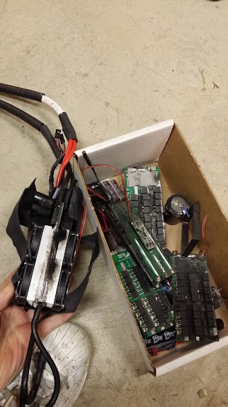
This amazed me, 12x TO247 FETs in an RC controller!! (I wish I would have tried to find the brand but I forgot to look) Wow!!! Sadly it was also blown.
Moar various large RC controller carnage box. These guys actually do this type of testing on a regular basis, and I was very fortunate to have them lend the time to help me get this tested as well as we were able to do.
I know this took a long time for me to get around to completing, I think some of you know what kind of hours I've been working, as well as taking an awesome vacation to Maui and getting married. I made a point of doing the best job I possibly could with the testing for you to try to make up for it.
Thank you Bruno (I will send it back to you if you want to take it apart further), and thank you JoeBen for helping, and other folks on the amazing Joby team. You are living the dream my friend.
Enjoy life,
-Luke
I'm fortunate to be friends with perhaps the most experienced and well equipped large scale RC motor controller testing team on the west coast. Here are a few pictures of some of the dyno-stands they were tinkering on when I arrived.
And a larger test running. Notice the big RC ESC's stuck under the front edge of the test stand.
We tried the controller on a number of different motors to find something it sync'd well with. Oddly, the larger Joby motors didn't hold sync well. For some reason the motor would occasionally buck or hicup a bit, and sometimes make a growling sound and shut down and need to be power-cycled to spin the motor again.
This was the largest outrunner I've ever got to play with. Feeling the unstoppable torque at lowest throttle setting on the large-pizza sized Joby blew it away though.
That's a room full of motor designers and motor control designing nerds. My kind of paradise.
When we found the JM1 motor was an excellent match for the controller (never lost sync, had excellent response and smooth torquey starting and relatively quiet operation (quiet for a trap controller, the motors are silent on sinus control). It also didn't show hicup'ing behavior while running the JM1, I'm not sure why.
Next step was selecting the best winding option to not over-load the controller for our first round of tests. I don't recall the exact kV, but I think it was close to 60-70kV.
The experts selected an appropriate load prop (I am not a prop calculator wizard like these guys) and mounted it up.
Then we mounted up the instrumentation and taped down the battery up top and taped down all the wires thoroughly, because the prop-wash from these things is like a tornado. The test stand measures not only input power to the controller, but also output power by measuring the reactive torque on the motor mount with slick strain-gauge setup and the RPM of the prop.
We did some baseline tests (sub 20amps, on a low impedance 40Ah battery at ~90V) to verify the instrumentation we wanted was working well, and that nothing was getting warm on the motor or controller (both stayed below ~35c running at 20amps, about 1800w for a minute).
Here is some video from the pre-run testing/tuning/confirming instrumentation etc.
[youtube]1OkKepn2toI[/youtube]
Now we start at just 30amps, then 50amps. It does fantastic. I interrupt the test early to check on it with the FLIR. It looks fairly cool from the surfaces you can see, which peak around 40degC (104F), pretty chill, and the fans were blowing slightly warm air. No issues for this power range, smooth control with no hicups or faults. We were all pleased and stoaked to see how it would do at step 2.
[youtube]LMCAB3o5Kw4[/youtube]
Then we began our second power handing test run targeting 100amps. It did do 100amps for longer than many RC controllers (you hear how excited we all were in the dyno room!), however as you can see from the plasma flashes I was lucky enough to catch on video it was not 100amp stable, though it did achieve it easily (not too many of the >12s RC ESC's can reach 100a before exploding.)
[youtube]J2ESeGcOVaw[/youtube]
We cut the shrink to see if by chance we could see what failed. The heatsinks immediately after shooting plasma weren't up to 100c. However, the fans did a good job of rapidly cooling them to like 40c again just a minute after it blew (the fans were powered by an external power supply that stayed running).
Looks like FET smoke to me.
I'm not going to be able to fix that easily to try again.
They had a few boxes of various other large RC controllers that performed similarly.
This amazed me, 12x TO247 FETs in an RC controller!! (I wish I would have tried to find the brand but I forgot to look) Wow!!! Sadly it was also blown.
Moar various large RC controller carnage box. These guys actually do this type of testing on a regular basis, and I was very fortunate to have them lend the time to help me get this tested as well as we were able to do.
I know this took a long time for me to get around to completing, I think some of you know what kind of hours I've been working, as well as taking an awesome vacation to Maui and getting married.
I made a point of doing the best job I possibly could with the testing for you to try to make up for it. Thank you Bruno (I will send it back to you if you want to take it apart further), and thank you JoeBen for helping, and other folks on the amazing Joby team. You are living the dream my friend.
Enjoy life,
-Luke
KMB
10 mW
Luke, Thank You!!
bigmoose
1 MW
Well thought out test to not allow a start transient to smoke it. Care in selecting a good motor match. Don't think the test method, supporting hardware or instrumentation can be criticized. Good to have friends in the industry! Thanks for the test, pix, video and write up. Full power torture test...
Interesting to see it fail at what seems a fairly low current on the face of it. I guess the answer is in the 100*C heatsink temperature you measured. It's clearly far too small and by the time you stack the thermal resistances the fet junction temperature must have been way over spec. And of course, at max. junction temp, current rating is zero...
I guess if the fets are being driven efficiently then there's nothing that can be done apart from increasing the heatsinking.
I guess if the fets are being driven efficiently then there's nothing that can be done apart from increasing the heatsinking.
Idontwanttopedal
1 kW
I think the newer esc has more fets in it now.
It doesn't matter how many FETs it has unless it uses better control topolagy it will fail at way below the ratings when used on a ebike.Idontwanttopedal said:I think the newer esc has more fets in it now.
nieles
10 kW
i think a better path for the heat to reach the heatsink is the first improvement needed. next on the list would be a bigger heat capacity for the heatsink
Thud
1 MW
luke says:
Nice work & wow, I would love to hang out at Joby for an afternoon blowing up chineese fireworks (controllers)
Married?........... the end is neigh. congrats BTW.
no one even noticed :lol:I know this took a long time for me to get around to completing,
Nice work & wow, I would love to hang out at Joby for an afternoon blowing up chineese fireworks (controllers)
Married?........... the end is neigh.
liveforphysics
100 TW
KMB said:Luke, Thank You!!
You're welcome. It's good to be getting my cue of tasks I've wanted to complete handled.
bigmoose said:Well thought out test to not allow a start transient to smoke it. Care in selecting a good motor match. Don't think the test method, supporting hardware or instrumentation can be criticized. Good to have friends in the industry! Thanks for the test, pix, video and write up. Full power torture test...
Thank you my friend. It was a lot work to try to do it in as favorable of a test setup as possible for seeing continuous power. The controller was right in that tornado of prop-wash as well as it's own fans, and the load was gentle and we crept up on it to try to create a best case power handing test for it. I was damn impressed to see it cranking out 9kw from that tiny package for as long as it did. I was also impressed to see that at 50amps (~4500w) it was fairly stable.
Punx0r said:Interesting to see it fail at what seems a fairly low current on the face of it. I guess the answer is in the 100*C heatsink temperature you measured. It's clearly far too small and by the time you stack the thermal resistances the fet junction temperature must have been way over spec. And of course, at max. junction temp, current rating is zero...
I guess if the fets are being driven efficiently then there's nothing that can be done apart from increasing the heatsinking.
Yeah, sadly it's common in the controller blowing world to see a heatsink at say 50-80degC while the FET dice are rapidly pushing past 180degC with the next step involving a transformation to plasma. Heatsinking is not something to underestimate.
Arlo1 said:Luke did you guys put a current sensor on a phase of the motor? It would be interesting to see how much over shoot it had. Thanks for the great test.
Nope, sorry my friend, they had an awesome very high speed capable tektronix phase-leg current probe and a badass isolated channel scope to be able to view phase voltage vs current, however I had my hands full with other aspects of the test and had to focus on the most important stuff only.
Arlo1 said:It doesn't matter how many FETs it has unless it uses better control topolagy it will fail at way below the ratings when used on a ebike.Idontwanttopedal said:I think the newer esc has more fets in it now.
Sadly, my experiences have shown me nothing to make me disagree with you Arlo.
nieles said:i think a better path for the heat to reach the heatsink is the first improvement needed. next on the list would be a bigger heat capacity for the heatsink
Modify one to be how you think it should, and send it to the Joby crew with a nice note on it to please test it for you, and you might get lucky and they donate there time and test chamber and many man-hours of labor to set it up and test it.
Thud said:luke says:no one even noticed :lol:I know this took a long time for me to get around to completing,
Nice work & wow, I would love to hang out at Joby for an afternoon blowing up chineese fireworks (controllers)
Married?........... the end is neigh.
Glad nobody noticed Thud.
Come visit me in paradise here in Santa Cruz and I will take you deep into the mountains to Joby's amazing nerd electric development commune, and my wife will have an amazing dinner waiting for us when we get home. Never thought I would be saying things involving the phrase "my wife", but it's a good thing. Similar threads
-
- Locked
- Replies
- 120
- Views
- 20,041
- Replies
- 2
- Views
- 1,355