
You are using an out of date browser. It may not display this or other websites correctly.
You should upgrade or use an alternative browser.
You should upgrade or use an alternative browser.
Efficiency?
- Thread starter DrkAngel
- Start date
John in CR
100 TW
Your Determining Peak Motor Output - Simple Cheap Method does not taking into account current limiting, so ambitious effort but no cigar since it won't work on any bike I own.
DrkAngel
1 GW
While I did make note of this ...John in CR said:Your Determining Peak Motor Output - Simple Cheap Method does not taking into account current limiting, so ambitious effort but no cigar since it won't work on any bike I own.
In my example, the motor shows capable of taking advantage of >90A at low rpm.DrkAngel said:(The exception is if the controller is of inadequate amps to allow maximum peak watt output.)
However, even with current limited to <35A, it is still capable of full Amperage at peak watt output point:
DrkAngel
1 GW
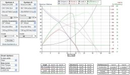
DrkAngel said:1. Determine no-load maximum motor speed - digital speedometer on motor wheel, blocked up (EG - 36mph)DrkAngel said:Observing the ebike.ca\simulator, I notice a consistent ~50% relation of input watts to watts output occurring at ~40% of no load motor speed.
Using this, it is possible to determine peak motor output.
2. Multiply no-load speed by 40% (EG - 36mph x .40 = 14.4mph)
3. Cruise near 14.4mph, Apply full throttle and note watt usage as speed hits-passes 14.4mph (1498w x .50 = 749w motor output)
(Precise 50% of input occurs at 38.6% of no-load speed- 13.9mph (this EG) ... but 40% is a fairly close, easy to figure number )
40% of no-load speed intersects 50% efficiency near the center of peak watt output nicely!
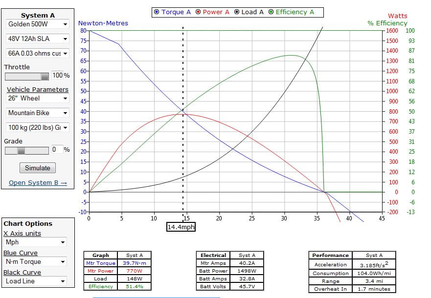
Surprisingly, this seems fairly consistent among all the simulations I have tried and looks to be a reasonably reliable measure.
"Reasonably" accurate!
Not precise but accurate within a few percentage.
(The exception is if the controller is of inadequate amps to allow maximum peak watt output.)
Update - I just sampled various-more motor types and found a variance of ~ 40% to almost 50% of no load speed as the peak watt output and 50% efficient point.
The 50% efficiency point remains firmly within the peak watt output region!
Up-Update -
The Clyte (Crystalyte) brand of motors seem to be the anomaly ... peak watt output shifted to 50% of no-load ... except for the TC-80 and TC-100.
These might be non-permanent magnet motors?
(S-Speed and T-torque windings are not specified ... in simulator ... possibly one type being the factor?)
There is such a clear shift of 50% efficiency that a differing motor type is clearly indicated!
The 50% efficiency point does remain firmly within the peak watt output region!
Ken Taylor
100 W
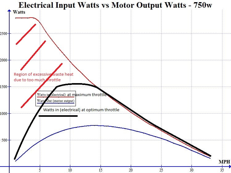
This graph is misleading and has been misinterpreted in this thread. It should be interpreted as a guide to how a throttle should be used at low speed and an argument in favour of phase current sensing in motor controllers.DrkAngel said:DrkAngel said:Thought I'd graph a direct comparison of the electrical watts supplied into a motor and the actual motor output (watts) power.
Based on a 750w motor at full throttle ...
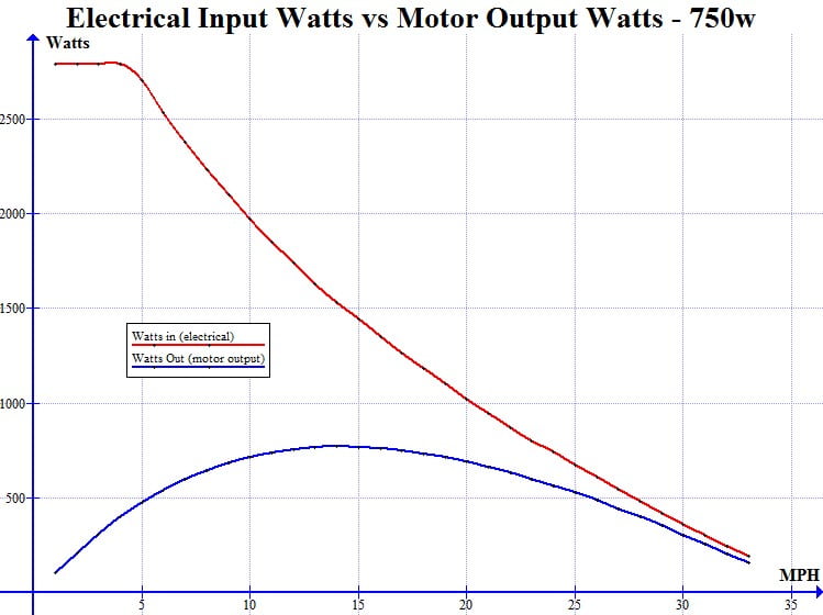
At 1mph energy efficiency is ~3% ... 97% wasted heat.
Increasing motor current will increase motor torque until maximum torque is achieved. The relationship is linear until close to maximum torque. Increasing amperage beyond this point generates only heat so should be avoided. Current measured before the controller is not the same as current measured after the controller where it is usually higher.
Power = torque x rotational speed so with a small rotational speed there is little useful power and nothing can be done about that, but what power there is, should be used because there is also less energy lost to friction and eddy currents the slower the motor runs. So the solution is to use very little throttle at low speeds as this will still provide maximum possible power but not overheat the motor.
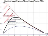
Reducing throttle reduces voltage seen by the motor and very little voltage is required to achieve high currents when rotating slowly as there is little back EMF. In practice it makes little difference when starting as extra power is wasted for only a few seconds while coming up to speed. On a hill it matters a lot. If the motor is struggling on a hill, throttle must be reduced as speed drops, the opposite to your natural inclination. A better solution is phase current limiting which takes the responsibility to reduce throttle at low speed away from the rider. With optimal throttle/phase current limiting the graph becomes something like:-
Attachments
John in CR
100 TW
Sorry Ken, but if your motor is getting bogged down on a hill then reducing throttle won't save the motor either. Assuming phase current control isn't an option, which it isn't with bargain controllers, then reducing pack voltage can help, because it that reduces phase current multiplication for the same power resulting in better efficiency at lower speeds. The real answer is a more powerful motor and/or a gearing reduction.
I live in a mountainous country and hills are a part of almost any ride. My rule of thumb is that if the bike can't maintain about 50% of top speed on the flats, then then hill is too steep regardless of throttle position, so it better be a short climb, because motor temps can get out of hand in tens of seconds.
I live in a mountainous country and hills are a part of almost any ride. My rule of thumb is that if the bike can't maintain about 50% of top speed on the flats, then then hill is too steep regardless of throttle position, so it better be a short climb, because motor temps can get out of hand in tens of seconds.
cal3thousand
10 MW
John in CR said:Sorry Ken, but if your motor is getting bogged down on a hill then reducing throttle won't save the motor either. Assuming phase current control isn't an option, which it isn't with bargain controllers, then reducing pack voltage can help, because it that reduces phase current multiplication for the same power resulting in better efficiency at lower speeds. The real answer is a more powerful motor and/or a gearing reduction.
I live in a mountainous country and hills are a part of almost any ride. My rule of thumb is that if the bike can't maintain about 50% of top speed on the flats, then then hill is too steep regardless of throttle position, so it better be a short climb, because motor temps can get out of hand in tens of seconds.
Absolutely the truth right there.
Ever try running a motor that is wound too fast for the wheel size? Doesn't matter how soft you baby the throttle, it will be inefficient all the way up to unloaded speed.
Ken Taylor
100 W
It's nice to get a response but I'm a little confused by those from John in CR and cal3thousand. First.
Yes, a motor that is run too slow can not produce much power but that isn't the misinterpretation I was claiming. I was claiming motors can run efficiently at low speed. Even a little extra power can help reduce the pedaling load. ThenJohn in CR said:The real answer is a more powerful motor and/or a gearing reduction.
Yes, that is entirely consistent with what I said. However, it will lower the output power at higher speeds so would not produce the same higher speed portion of the "Watts out" curve in the graph.John in CR said:reducing pack voltage can help, because it that reduces phase current multiplication for the same power resulting in better efficiency at lower speeds.
That's where I'm confused as it is inconsistent with the other statement. Reducing the throttle has the same effect as reducing pack voltage with most controllers. Reducing the throttle sufficiently will definitely save the motor from overheating.John in CR said:Sorry Ken, but if your motor is getting bogged down on a hill then reducing throttle won't save the motor either.
That's got me more confused. Regardless of the wind there must be somewhere it hits peak efficiency before unload speed.cal3thousand said:Ever try running a motor that is wound too fast for the wheel size? Doesn't matter how soft you baby the throttle, it will be inefficient all the way up to unloaded speed.
Reducing the throttle has the effect of shifting the efficiency curve downwards, like you got hold of the high speed end of the graph and pushed it back keeping the low end in the same place. You therefore get slightly better efficiency in the lower speed range, but depending how your controller works, it will probably reduce current too, so you get less torque. I would guess that if you're struggling to get up a hill, reducing the throttle won't be an option, but if you have plenty of power, reducing the speed will improve efficiency and your motor won't heat up so much.
DrkAngel
1 GW
Reducing throttle, typically, does increase efficiency, however ...
there comes the point of not enough (output) watts to accomplish anything!
Regearing non-hub or rewinding hub motors to maintain 40%+ of no-load speed on steepest hills is important for efficiency ... and saving motor ...
See - Attack them Hills!
Sadly, this might limit top speed on the level ...
Ideal, without compromising performance, solution would be multiple motor gears.
Simplest is a mid-drive set-up, running through the rear wheel sprockets ...
See -Crankin' It - Mid-Mounted Crank Drive
cal3thousand
10 MW
Ken Taylor said:It's nice to get a response but I'm a little confused by those from John in CR and cal3thousand. First.
Yes, a motor that is run too slow can not produce much power but that isn't the misinterpretation I was claiming. I was claiming motors can run efficiently at low speed. Even a little extra power can help reduce the pedaling load. ThenJohn in CR said:The real answer is a more powerful motor and/or a gearing reduction.
Yes, that is entirely consistent with what I said. However, it will lower the output power at higher speeds so would not produce the same higher speed portion of the "Watts out" curve in the graph.John in CR said:reducing pack voltage can help, because it that reduces phase current multiplication for the same power resulting in better efficiency at lower speeds.
That's where I'm confused as it is inconsistent with the other statement. Reducing the throttle has the same effect as reducing pack voltage with most controllers. Reducing the throttle sufficiently will definitely save the motor from overheating.John in CR said:Sorry Ken, but if your motor is getting bogged down on a hill then reducing throttle won't save the motor either.
That's got me more confused. Regardless of the wind there must be somewhere it hits peak efficiency before unload speed.cal3thousand said:Ever try running a motor that is wound too fast for the wheel size? Doesn't matter how soft you baby the throttle, it will be inefficient all the way up to unloaded speed.
Peak efficiency doesn't ever mean high efficiency. It just means the most you are going to get.
What I'm saying is: The slower a motor runs vs. it's natural unloaded speed, the more inefficient you will be. Take the extreme case of a motor running up a hill so steep that it moves 1 inch in 1 minute. All it's doing is creating heat.
Ken Taylor
100 W
Thanks for the responses to my suggestion this thread is misleading. It seems I haven't convinced many. I'll try again.
I was motivated by reading a comment from justin_le where he said"-
Further down this is moderated by:-
In my view the best advice is:-
Unless your controller limits phase current, reduce throttle at low speed. Use less throttle the slower you go. At any speed there is a throttle setting that allows you to extract maximum possible power from the motor without producing any more heat than would be produced at normal speeds. At low speeds, motor power is reduced and the optimum throttle setting is hard to estimate. It is common for the rider that wants more power to use too much throttle and if you do use too much throttle the motor will heat up. If it is only done for a few seconds it is OK.
This means that it is sensible to use power from rest and that any hill that you can climb by pedaling alone can be made easier with some assist.
This doesn't contradict the advice "the application of pedal assist combined with moderated throttle can deliver satisfactory acceleration..." but that is subtle compared to "At 1mph energy efficiency is ~3% ... 97% wasted heat" from which the thinking that causes "a lot of people who don't use their throttle until after pedaling up to speed because supposedly they've been told that throttling off the line wastes a huge amount of power" might emanate.
I was motivated by reading a comment from justin_le where he said"-
The suggestion being that with his new trip analysis software people would discover:-justin_le said:For instance I know a lot of people who don't use their throttle until after pedaling up to speed because supposedly they've been told that throttling off the line wastes a huge amount of power.
I'm then thinking; as useful as good analytics can be, this wasn't a good example as people don't think "throttling off the line wastes a huge amount of power". I then come across this thread and blow me down; it says:-justin_le said:... when you look at all the net watt-hours used on the average ebike trip, your initial starting acceleration after each stop will only account for a tiny fraction of that, and that throwing away this most useful aspect of the ebike away (getting quickly up to speed) doesn't buy much in return.
with a graph to prove it. In my view it is misleading because that graph assumes wide open throttle.DrkAngel said:At 1mph energy efficiency is ~3% ... 97% wasted heat...
Further down this is moderated by:-
Here I would only disagree with "Of course this will limit acceleration" because with the optimum throttle setting, the blue Watts Out line in the graph is unchanged, only the red Watts in line is reduced. Therefore reducing throttle to the optimum level does not limit output power and therefore does not "limit acceleration".DrkAngel said:The good news?DrkAngel said:Yes efficiency at low speeds is horrific!!!
Inefficiency can be regulated through the use of throttle restraint!
At most any speed maximum efficiency is attainable.
Of course this will limit acceleration ...
But, since the worst region is from a standstill till mid-speed, the application of pedal assist combined with moderated throttle can deliver satisfactory acceleration...
In my view the best advice is:-
Unless your controller limits phase current, reduce throttle at low speed. Use less throttle the slower you go. At any speed there is a throttle setting that allows you to extract maximum possible power from the motor without producing any more heat than would be produced at normal speeds. At low speeds, motor power is reduced and the optimum throttle setting is hard to estimate. It is common for the rider that wants more power to use too much throttle and if you do use too much throttle the motor will heat up. If it is only done for a few seconds it is OK.
This means that it is sensible to use power from rest and that any hill that you can climb by pedaling alone can be made easier with some assist.
This doesn't contradict the advice "the application of pedal assist combined with moderated throttle can deliver satisfactory acceleration..." but that is subtle compared to "At 1mph energy efficiency is ~3% ... 97% wasted heat" from which the thinking that causes "a lot of people who don't use their throttle until after pedaling up to speed because supposedly they've been told that throttling off the line wastes a huge amount of power" might emanate.
DrkAngel
1 GW
I've always recommended restrained throttle combined with pedal assist, from a dead stop ...
For those incapable of throttle restraint, I recommend a reduced amperage controller.
Full throttle - 50A vs 30A Controller

At sub 40% speed, amperage, (effectively = throttle), is forcibly limited.
Peak motor output and top speed are not affected!
I have produced an eZip upgrade, 24v to 36V, with abnormally prolonged lifespan, by replacing the 24V 35A controller with a 36V 25A controller.
Low speed full throttle acceleration (and heat production) is similar to the 24V 35A, but higher speed, in more efficient (less damaging) region is increased.
This graph, reasonably accurately, represents my project. (Produced with eBikes.ca/simulator)
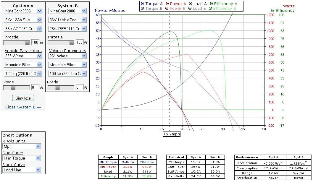
While others, upgrading this bike, suffered overheats and "burnt ups", my bike has survived several thousand miles and 5+ years of use.
For those incapable of throttle restraint, I recommend a reduced amperage controller.
Full throttle - 50A vs 30A Controller
At sub 40% speed, amperage, (effectively = throttle), is forcibly limited.
Peak motor output and top speed are not affected!
I have produced an eZip upgrade, 24v to 36V, with abnormally prolonged lifespan, by replacing the 24V 35A controller with a 36V 25A controller.
Low speed full throttle acceleration (and heat production) is similar to the 24V 35A, but higher speed, in more efficient (less damaging) region is increased.
This graph, reasonably accurately, represents my project. (Produced with eBikes.ca/simulator)
While others, upgrading this bike, suffered overheats and "burnt ups", my bike has survived several thousand miles and 5+ years of use.
Attachments
John in CR
100 TW
cal3thousand said:Yes, that is entirely consistent with what I said. However, it will lower the output power at higher speeds so would not produce the same higher speed portion of the "Watts out" curve in the graph.John in CR said:reducing pack voltage can help, because it that reduces phase current multiplication for the same power resulting in better efficiency at lower speeds.
That's where I'm confused as it is inconsistent with the other statement. Reducing the throttle has the same effect as reducing pack voltage with most controllers. Reducing the throttle sufficiently will definitely save the motor from overheating.John in CR said:Sorry Ken, but if your motor is getting bogged down on a hill then reducing throttle won't save the motor either.
Lower throttle position doesn't exactly equal lower voltage. It approximates it pretty well under low load conditions, but that breaks down on hills due to spiking phase currents. If it's not putting your motor at greater risk, then it's still putting your controller at risk.
liveforphysics
100 TW
John nailed it. With the typical speed control based ebike controller, all you change with the throttle is the target speed. The controller dumps everything it has up to its current limits into achieving that speed. It makes extremely high power low weight bikes unrideable. When I ran a 1200A controller to a Perm132 setup on 25S lipo on my bicycle, we had a single attempt of speed-based throttle and immediately realized only torque control throttle.
Ken Taylor
100 W
Wow, I'm privileged to get feedback from the elite here and liveforphysics is a ruthless critic who I've never observed to be in error. I'll push on, in the expectation I'll get my arse kicked and learn something.
and that
Yes and I hope nothing I've written has appeared to contradict this. However when it is said:-DrkAngel said:I've always recommended restrained throttle combined with pedal assist, from a dead stop ...
I disagree. They are often referred to as speed based controllers but they aren't. They control the voltage seen by the motor. I realise there are limitations in that model but to quote the guy wholiveforphysics said:With the typical speed control based ebike controller, all you change with the throttle is the target speed.
:-liveforphysics said:nailed it
and that is also my understanding. When liveforphysics says:-John in CR said:Lower throttle position doesn't exactly equal lower voltage. It approximates it pretty well under low load conditions
I'd say it doesn't. That would require a feedback loop which varied motor voltage with speed. It is an open loop controller and the speed at any throttle position depends on the motor characteristics and load. On a low power motor you will get a significant reduction in speed on an appropriate hill that can be recovered by increasing the throttle. This is what cruise control does, using a feedback loop. On high power motors and low weight bikes the motor characteristics are such that speed as a function of throttle position is a good approximation which is whatliveforphysics said:The controller dumps everything it has up to its current limits into achieving that speed.
So where I think I'm most exposed is in defining what representsliveforphysics said:makes extremely high power low weight bikes unrideable. When I ran a 1200A controller to a Perm132 setup on 25S lipo on my bicycle, we had a single attempt of speed-based throttle and immediately realized only torque control throttle.
I think it is everywhere on the "watts in (electrical) at optimal throttle" curve on this graph:-John in CR said:low load conditions
and that
only in the region of "excessive waste heat due to too much throttle" on the graph, which I recommend trying to avoid.John in CR said:...that breaks down ... due to spiking phase currents.
For speed-control controllers, you can say that the throttle position equates to a target speed. The throttle doesn't really control voltage to the motor. The battery is connected directly ro the phase wires. All the controller can do is open and close the FETs, so it always allows battery voltage to the motor. It's the time interval on the pulses that it changes, which in my way of thinking is the current, although some would argue that it's the average voltage that's reduced. I guess it's really the power. The actual voltage and current that the windings see is rather more complicated because the capacitors have to charge and discharge, and the coil windings have inductance.
DrkAngel
1 GW
A "normal" PWM controller emulates reduced voltage rather well.
Partial throttle reduces the frequency and, or, duration of full current pulses.
Sufficient cap capacity could closely match lower voltage.
An "abnormal" "speed control based ebike controller", on the other hand, apparently, dumps full uninterrupted current into the motor until some speed sensor indicates target speed ?
... tends to negate a primary function of the throttle ... ?
Partial throttle reduces the frequency and, or, duration of full current pulses.
Sufficient cap capacity could closely match lower voltage.
An "abnormal" "speed control based ebike controller", on the other hand, apparently, dumps full uninterrupted current into the motor until some speed sensor indicates target speed ?
Sounds like an expensive programmable controller programmed ... badly!liveforphysics said:... With the typical speed control based ebike controller, all you change with the throttle is the target speed. The controller dumps everything it has up to its current limits into achieving that speed. ....
... tends to negate a primary function of the throttle ... ?
DrkAngel
1 GW
Added Load lines to 750w full throttle watt input/output motor graph.


Maximum speed can be shifted by altering gear ratio.
Hub motor by differing wheel size.
Maximum speed can be shifted by altering gear ratio.
Hub motor by differing wheel size.
DrkAngel
1 GW
Example-proof of full current maximum output at ~50% efficiency.
"500w" Bafang crank drive motor:
Notice! 48V 20A = 960w (input) = Rated 48V 500w (output)
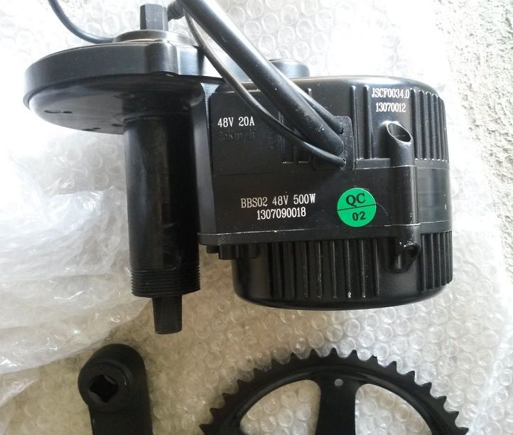
With full amp motor systems:
controller is capable of enough amps to provide the maximum possible watt output
maximum watt output is typically at 40% of motors no load speed and ~50% efficiency
Although a full Amp motor system will supply full possible watt output from e.g. 20A, At 0 rpm the motor is capable of much higher input (60-80A ,,, possibly more)
Increasing amps will neither increase top speed or maximum motor output!
It can, improve acceleration to mid speed, ... at the sacrifice of energy efficiency and increased heat production ...
"500w" Bafang crank drive motor:
Notice! 48V 20A = 960w (input) = Rated 48V 500w (output)
With full amp motor systems:
controller is capable of enough amps to provide the maximum possible watt output
maximum watt output is typically at 40% of motors no load speed and ~50% efficiency
Although a full Amp motor system will supply full possible watt output from e.g. 20A, At 0 rpm the motor is capable of much higher input (60-80A ,,, possibly more)
Increasing amps will neither increase top speed or maximum motor output!
It can, improve acceleration to mid speed, ... at the sacrifice of energy efficiency and increased heat production ...
raphm
100 mW
- Joined
- Jan 19, 2016
- Messages
- 38
Take care that at low RPM, you can reach motor saturation. In a good system, input electrical power is more limited at low speed than at higher speed to avoid saturation.Although a full Amp motor system will supply full possible watt output from e.g. 20A, At 0 rpm the motor is capable of much higher input (60-80A ,,, possibly more)
I think it depends on the system, with a high power battery (low internal resistance) and if you don't reach motor saturation, increasing amps should increase maximum motor output power.Increasing amps will neither increase top speed or maximum motor output!
You also need to consider steep slopes where increasing amps allows to keep appropriate speed and improve efficiency.It can, improve acceleration to mid speed, ... at the sacrifice of energy efficiency and increased heat production ...
DrkAngel
1 GW
Motor Watt Output "mapped" by current limiting
"Full" Current - Motor of same rated output watts will have better acceleration, climbing ability but lower attainable speed.
With sufficient amps, the typical electric motor outputs maximum watts at about 40% of no load speed.
Nearly universally this corresponds to a 50% efficiency!
So, a 1000w input ... outputting 500w usable energy + 500w wasted-damaging heat.
Efficiency, at full throttle, above this speed increases till top speed but motor watt output declines.
This is effective for varied terrain.
The motor has greater output capability as it begins to slow when engaging a hill.
Best applicable to multi-terrain eBikes, Mountain Bikes for hilly roads etc.
Current limiting - Motor of same rated output watts will be more speed capable.
In order to increase efficiency and reduce weight and cost, the same motor can use lighter windings and reduced amp controller to limit low speed watt output.
Maximum motor output might occur at 80% of no load speed and 80% efficiency.
Decreasing amps will maintain the same top speed but rather than decreasing efficiency + increasing motor watt output when engaging a hill, efficiency decreases and motor output decreases.
Common with most RC flight motors.
Very susceptible to damage from exceeding rated "watts".
Best applicable to eaBikes, eBikes for level terrain or mid-drives with multispeeds.
Alan B
100 GW
It is unfortunate that Justin's wonderful simulator is not graphing at equilibrium.
It presents useful info but in a confusing way. At full throttle, and without controller current limiting, and assuming the motor doesn't saturate. So many things are carefully calibrated about Justin's data, and yet a few things are not modelled completely in this wonderful tool.
At only one point on the graph is the information statically correct, where the load line crosses the power output.
Everywhere else it is a snapshot of a moving system, so conclusions drawn from all other points are very easily misunderstood because they are in a dynamic situation, and the dynamics are not accounted for. For example the efficiency at low speed fails to take into account the acceleration of the system. So the energy is producing work plus acceleration. But the acceleration is not shown and ignored. So people look at it and assume the efficiency is very low. It is only part of the picture. Most of the work is going into acceleration, but the acceleration is not shown. So there is missing energy.
These simple ebike controllers are generally PWM throttle type, so the throttle sets the PWM, generally with an overcurrent override. So at low speed you twist the throttle and it controls the PWM directly up to the point the controller figures the current is getting too high, then the controller stops increasing the PWM there. Beyond that the throttle does nothing at all, the controller controls the PWM at what it considers the max current.
The effective motor voltage is battery voltage times PWM where PWM is a zero to one value. So when you twist the throttle you are effectively controlling motor voltage. Some people say that it is a speed throttle because the motor voltage controls the unloaded motor speed in a direct fashion. But the loading factors reduce the actual speed, and depending on the motor vs load it can be a little or a lot. So it sort of is a speed throttle, but not a very good one if the motor is weak compared to the power needed, but if you have a very strong motor for the loading then it is a fairly decent speed throttle (but still open loop).
Here's something that may help folks understand motors a bit more easily.
Simple Motor Model
Motor has resistance (which depends on temperature, when it gets hotter the resistance goes up).
Motor has Back EMF which is a voltage that depends on motor speed. As speed rises, back EMF rises.
Throttle controls PWM which controls Voltage applied to Motor, from zero up to battery voltage (subject to the controller stepping in and clamping the PWM when it decides that battery or motor currents are getting too high).
Current in the motor makes torque. Increasing the current linearly increases the torque up to the saturation level beyond which increasing current produces very little additional torque. We don't want to operate beyond saturation because it is much less efficient.
Heating in motor is primarily from current squared times motor resistance. So increasing current increases heat much faster than it increases torque. We want to use the minimum current to get the job done.
Current in the motor is produced from the difference between the applied voltage and the back EMF, this difference divided by the motor resistance makes motor current. The difference voltage that makes full torque is fairly small, perhaps 5-10 volts for an ebike motor. The rest is used to overcome back EMF. This small range is where we can control the torque with the throttle. This is why the throttle is touchy, only a small change of voltage goes from zero to full torque.
So the motor's back EMF subtracts from the voltage that the throttle delivers, and what's left drives the motor's resistance. As we increase in speed we eventually "run out" of voltage to overcome the increasing back EMF and the system tops out for that load.
DrkAngel
1 GW
Take a better look at the eBike Simulator!Alan B said:It is unfortunate that Justin's wonderful simulator is not graphing at equilibrium.
It presents useful info but in a confusing way. At full throttle, and without controller current limiting, and assuming the motor doesn't saturate. So many things are carefully calibrated about Justin's data, and yet a few things are not modelled completely in this wonderful tool.
Throttle has slider to emulate 0 to 100%.
and
Controller current limiting can be adjusted using "custom controller" option.
Alan B
100 GW
Of course, but to get the "real" data across the throttle range you have to run the simulator many times, and use tricks to get the correct value of motor current. This is not using the users' time efficiently and most users won't do it or even know how to.
The way the data is presented confuses people and they get the wrong conclusions. Constantly.
It is essentially the graph of an experiment where the data is valid at one point, the equilibrium point. Data to the right of that is not real, the motor won't get there, data to the left of that point is not in equilibrium, accelerating, moving toward equilibrium.
If you want to know the efficiency, power, current of a motor across the speed/throttle range you have to vary the throttle and rerun the simulator for each throttle setting, collect the equilibrium data and then replot the results.
Each time I want data from the simulator I have to run it dozens of times to get that info. It could be so much more efficient of the users's time.
The simulator could do this for you, and then it would be instantly a lot more useful, and people would not get the wrong conclusions as often. It could be an option for the display format, not to replace the existing graphs, but for most people it would be directly more useful.
Computers are good at doing this. Why not offer the improved option?
Let's take a direct example. Your first post in this thread says the efficiency of the motor with WOT at 1 mph is 3%. This is simply wrong. You were misled by the graph. If you drop the throttle to get equilibrium at 1 mph the efficiency will be about 10 times higher, around 30 percent (for the default motor in the sim). The extra energy at WOT is going into acceleration, and the efficiency graph IS NOT TAKING THIS INTO ACCOUNT. Much of the extra energy is not lost, it is accelerating the bike and rider. The efficiency graph is misleading. It is calculating efficiency in a way that ignores the acceleration component. Interpreting this data correctly is not easy.
While I'm brainstorming,
Since this simulator is for ebikes it would be nice to have rider inputs available, and second and perhaps third motors, and mid drives with gearing. It is quite interesting how much difference a few watts from the rider makes, and this could easily be added.
The simulator is a great tool. It could be a lot more.
Similar threads
- Replies
- 0
- Views
- 123
- Replies
- 10
- Views
- 543

- Replies
- 12
- Views
- 10,401
- Replies
- 3
- Views
- 402