dutchlincoln said:
Today i had my first drive with the BMS.
I have to set the current and match it to a reference value, so its probably not exact yet.
What bothers me, is this:
I have fully charged the pack, charging current was 9 amps, so this could be quite correct.
When full, i reset the pack value, so all was 90Ah.
When i put on my contact, and turned my headlight on, it states approx. 0.2A, so a little on the low side.
When i give some gas, current flies up. When i brke with regen braking, it gives negetive current, so sensor is correct connected.
Today however, i started with 90Ah capacity, and when i arrived at work, i had a battery of 90Ah, and current state of charge was 103Ah!!
When i drove back home, my state of charge is 118Ah!
So, when i use power, it adds up the value????
Anyone can tell me what i've done wrong? (no time to check now, i have to leave again).
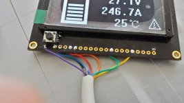
ps. Today i noticed the Oled display going crazy on me.
Yesterday in my heated barn it all worked fine.
Today when i arrived at work, i took a peek on the display when it wouldn't go on...
I trid contact on and off several times, but no response.
When i tried 15 min. after, it went on, but the last few millimeters on the display were flickering and giving weird caracters.
When i tried again around noon, it wouldn't start, and after 4 times trying, it worked fine.
Today i arrived at home, no display again. When i tried it for the second time, it gave the weird caracters again.
In the evening i went away, and when i (just) returned and put the charger on it, the top 5 millimeters flickered and gave weird caracters again.
Anybody got an idea what that can be?
It seems i have a bit bad luck with the BMS... Maybe manufactured on monday morning? :lol:
Eason! Where are you!!??? I need you pls!
Sorry for my leaving for a few days.You are right,I am having a bussniss trip and just back to office.
On my bussness trip,I can just read email.If possible,send me e-mail and I can reply you in time.
.I read the BBS carefully,at first,there are wrong voltage with the first chip,but it seems all right after you setup the right software.
1.your battery is 90AH,after you drove back home,it shows 118Ah.
It is probably the problem with the external hall sensor.
Can you see the arrow on the external hall sensor?
This is the direction of discharging.
If the sensor is connected in the negative direction,when discharging,BMS thinks it is charging,so SOC will add up.
Please check the external hall sensor.The direction of arrow is the direction of discharging.

")