Cycle Analyst V3 preview and first beta release

teklektik said:
I ran some tests last night and this morning and could not duplicate the Watts/Amps difference - but it seems that symptom was really not in play - so, okay on that count.

The Gas Gauge is a software artifact so if your CA is showing the proper voltage, there is no hardware failure that could reasonably be causing this (I don't think...). Since it persists across a reflash, it sounds like an EEPROM or configuration issue.

I know the State of Charge gets written to EEPROM on power down, so I was wondering if you had some hinky value stored away that is giving it problems. But - the SOC value should be blitzed on a re-flash since it's not in the calibration parameter section of memory - so that sort of makes the EEPROM idea invalid.

But - the Gas Gauge uses a kind of interesting algorithm that combines historical Ah and open circuit voltage to track the SOC under all circumstances. It actually switches modes and looks at the open circuit voltage when the bike has no (little) current draw since that's the only time the voltage is close to 'open circuit'. It then looks up the OC voltage in a table (by chemistry) and determines the SOC. It generally takes a bit of time when it's making adjustments to the accumulated Ah reading (which is error-prone) to correct it to the more accurate SOC derived from the OC voltage.

  • So - I''m wondering if you need to zero your amps so the CA can get a proper opportunity to do the OC voltage measure/correction to the SOC. If you have a non-zero 'idle current' it may not be doing the gauge update because it thinks the voltage reading will not really reflect OC.
    Just a guess - try the Zero Amps trick.
Failing that - maybe some more info:
Do the voltage and Ah read correctly?
What is the computed RBatt after a ride?
What are your battery config settings?
Thanks for the advice Teklektik..I'll try zeroing the amps in the morning and if that fails, I will grab that other info while the turkey is smoking...
Much appreciated;)
 
I would like to know the specs on the external power plug coming out of the CA. I read on grin's website about using the CA to power lights and that it puts out 12.8v, but now when I look in the manual it sounds like it puts out the full voltage of the battery limited to 1A by a fuse.

I would like to power 2 lights on my handlebars with the CA if possible, they draw 2 amps each at 8.4 volts. At 12.8v my lights should draw about 1.3 amps each so 2.6amps total. Can the CA's external power plug support 2.6 amps if it puts out 12.8 volts?

These are the lights I have ordered if more information is needed. http://www.lights-box.com/uniquefir...-headlamp-with-4-18650-battery-pack-red-color

I also have a rear light but I think I will power it a diffrent way because if I power it from the CA it defeats the purpose of keeping the number wires going to the handlebars down.
 
I believe you will need to use a dc-dc convertor to drop your battery voltage via CAV3 accessory output. 'don't think it can be scaled down?

While 'should be okay with regard to current draw of dc-dc convertor supplying 12V/1.6A it begs the question, why not merely connect a dc-dc directly to the battery pack and wire 12V output to the lights?
 
wyvernwaddell said:
teklektik said:
I ran some tests last night and this morning and could not duplicate the Watts/Amps difference - but it seems that symptom was really not in play - so, okay on that count.

The Gas Gauge is a software artifact so if your CA is showing the proper voltage, there is no hardware failure that could reasonably be causing this (I don't think...). Since it persists across a reflash, it sounds like an EEPROM or configuration issue.

I know the State of Charge gets written to EEPROM on power down, so I was wondering if you had some hinky value stored away that is giving it problems. But - the SOC value should be blitzed on a re-flash since it's not in the calibration parameter section of memory - so that sort of makes the EEPROM idea invalid.

But - the Gas Gauge uses a kind of interesting algorithm that combines historical Ah and open circuit voltage to track the SOC under all circumstances. It actually switches modes and looks at the open circuit voltage when the bike has no (little) current draw since that's the only time the voltage is close to 'open circuit'. It then looks up the OC voltage in a table (by chemistry) and determines the SOC. It generally takes a bit of time when it's making adjustments to the accumulated Ah reading (which is error-prone) to correct it to the more accurate SOC derived from the OC voltage.

  • So - I''m wondering if you need to zero your amps so the CA can get a proper opportunity to do the OC voltage measure/correction to the SOC. If you have a non-zero 'idle current' it may not be doing the gauge update because it thinks the voltage reading will not really reflect OC.
    Just a guess - try the Zero Amps trick.
Failing that - maybe some more info:
Do the voltage and Ah read correctly?
What is the computed RBatt after a ride?
What are your battery config settings?
Thanks for the advice Teklektik..I'll try zeroing the amps in the morning and if that fails, I will grab that other info while the turkey is smoking...
Much appreciated;)
Seems like zeroing the amps did the trick.. Everything is copacetic today.
Thank you Teklektik for the excellent advice. Let me know if you're ever around Jacksonville, FL...I owe you a beer, I do!
 
Scott said:
I would like to know the specs on the external power plug coming out of the CA. I read on grin's website about using the CA to power lights and that it puts out 12.8v, but now when I look in the manual it sounds like it puts out the full voltage of the battery limited to 1A by a fuse.

The web site does not claim the CA Aux Power connector delivers 12.8v, but rather that the Cycle Lumenator internal DC/DC converter delivers 12.8v. The V3 Guide is correct.

ebikes.ca said:
Power from Cycle Analyst
The included 5.5x2.1mm DC Power cable can be wired directly from the Cycle Analyst by opening the CA and soldering the red and black wires to the CA's V+ and Ground pads. Since the CA and Lumenator are usually both located on the front handlebars, this saves running the cable down to the battery pack. If you don't have a Cycle Analyst, you can make an Anderson Powerpole tap for use with Powerpole systems, or wire in to whatever connectors or terminals you have available on your battery.

Input Power
The internal DC-DC converter of the Cycle Lumenator efficiently steps down any input voltage in the range 15-100V into a constant 750mA current source driving the four Cree XP-G LEDs in series at about 12.8V. Click on the graph to the left to see the input current requirements of the light over its full input voltage range.
 
Does anyone know how to do a "full reset" on a cycle analyst v3. I held the reset for over 10 seconds after doing a normal reset, yet it does not do a full reset?
 
teklektik said:
Not sure what you are looking for.
Please describe what did not reset.

I want to reset the total miles and amp hour of the batteries. In the manual for v2 it says there is a "full reset" option where you hold the button for 6 seconds after a normal reset. However, it does nothing.
 
EdwardNY said:
I want to reset the total miles and amp hour of the batteries. In the manual for v2 it says there is a "full reset" option where you hold the button for 6 seconds after a normal reset. However, it does nothing.
You will have more success using the manual for the V3 instead of the V2. Please download the Unofficial Guide + Errata documents. Reset options are described in section 2.1.

There is no V2-style "Full Reset" option in the V3. The V2 supports historical lifetime statistics for only a single battery - the V3 supports two and switching presets replaces resetting the parameter suite for only one battery. If you wish to reset the battery statistics you will need to go to Setup and manually reset them.

Although some may disagree, making it difficult in the V3 to lose lifetime statistics by an accidental reset operation appears as a feature.
 
Hello,

I have a CA3 together with an em3ev 29E triangle 48V battery and have two questions:
  • How can I set up the CA so that the battery only gets discharged down to 10%? (Paul said keeping the battery in a charge level between 10 and 90% prolongus its lifetime)
  • CA3 seems to add more cycles to the battery. I charged it 3 times and it shows 5 cycles. How does this happen?
Thank you very much :) and sorry in case the answers are already digged into that long thread :oops:
 
I can confirm the latest Prelim6 firmware is installed already, but re-uploaded it anyway. Big green Successful box. still intermittent boot. Could this be a hardware tolerance thing? perhaps a wrong value component somewhere? The sympton is that the backlight flashes quite brightly, then dims, but the boot screen on the CAV3 does not display any text.

I'd like to have this turn on reliably.

Thanks
Andy
 
If you search in the thread you will see a mention of two of this. The cause is unknown at this time as far as I know. My bike has done this since day one with different V3s, so there is likely some characteristic of the build that is causing it. Considering the number of V3s out there, the problem is rare and Justin has been unable to replicate it in the lab. This makes problem resolution very difficult.

If you are troubled by a product issue, ES is never the best place to go first. You should email ebikes.ca and pursue it there.
 
I'm reporting what is a new experience, at least for me. I have a bike on a stand (trainer type of thing), with the rear wheel (containing Crystalyte HT3525 hubmotor) spinning freely (no resistive load other than motor windings). I'm using a 12 FET 3077 MOSFET Extreme Modder Controller LYEN Edition controller and 48V 10.5aHr LiMn battery pack. When I first put all the components together, the CAv3-prelim6 (connected directly to the controller, using the controller's internal shunt), the CA firmware was 'hosed' -- it wouldn't allow entry of the correct RShunt value, etc. (described in detail in a post above). I fixed this using teklektic's "Double Flash" method, and everything worked fine. Yesterday I had another person powering the bike (I'd say "pedal", but it's a "rowing bike" and doesn't have pedals), making the rear wheel/motor spin freely, with the system (ignition) being in the OFF position (no battery power supplied). All other electrical connections, however, remained connected as if the bike were being used in electric power mode. Spinning the rear wheel at sufficient speeds made the CA "light up" (begin the boot process), but then it would go off again as the wheel speed decreased/stopped. When I next powered up the system (turning the battery ignition key to ON, I got the dreaded "Low V" display message again after the initial splash screen on the CA. Going into the CA's programming mode revealed that all my previous settings of consequence were again 'hosed'. I'm guessing that doing the "Double Flash" will again restore the CA to factory defaults, allowing me to re-enter my previous values. This scenario produces two questions from me:

1) Is what I did (human powering bike with ignition OFF) a No-No that I missed the warnings for somewhere, or should this not have had the results I described above?

2) Is there a program out there that let's me manipulate (view & edit) the firmware *.hex files, especially the user-settable parts like wheel circumference, battery chemistry, motor pole count, etc., so that I can 'save' my settings and make it easier to reflash the CA with my customized hex files when it becomes necessary? I've been a professional programmer in a previous life, and I guess I'm volunteering to work on such a program if it doesn't already exist.

I've not yet re-flashed the CA in the event that someone has suggestions for doing additional debugging or documentation before I change anything. tia ... hj
 
Joe Perez said:
teklektik said:
Config parm summary updated to reflect additional linear sensor parameters...
Thanks for that- this had been causing me some consternation prior to actually receiving the unit and seeing how it worked.

Also, a note on the use of "other" temp sensors:

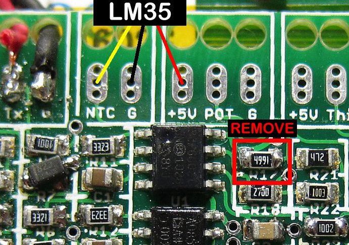
I'm awaiting the delivery of a MAC motor from Cell-Man. These motors are fitted with an LM35 temperature sensor, which is different from either the LM335 or the NTC thermistor that Justin suggests. Specifically, thermistors and LM335s act like resistors or zener diodes, which conduct current to ground depending on temperature. As such the CA-3 is fitted with a pullup resistor on the "NTC" pad. Although the part number seems quite similar (LM35 vs. LM335), these devices are quite different.

The LM35 is an active device, which outputs a positive voltage which varies with temperature. Cell_Man selected this device over the passive devices which Justin suggested to enable folks without CAs to use a simple voltmeter to measure temperature (the LM35 outputs 10mv / °C, so it reads nicely on even a simple $5 voltmeter.) However the internal architecture of the LM35 is such that it won't work properly with a pullup voltage applied to its output- it can only source current, not sink it.

So, to use one of these devices, you need to remove the pullup resistor (R17) from the CA board. It's a tiny little surface-mount part, but shouldn't be too difficult if you have a pair of irons to lift it up tweezer-style:

n7zJq.jpg


Having removed this resistor, you can pick up 5v at the adjacent pad to supply operating power to the LM35, and then calibrate the software for 0 degrees = 0 volts and 100 degrees = 1 volt.


EDIT:

The NTC input on the CA tends to float high when unconnected, or when connected to a device which cannot sink current to ground on its output such as the LM35. With the circuit configured as described above, I saw false-high readings of 100 degrees or more, just from the stray voltages floating around the circuit.

This has been solved by simply placing a pull-down resistor between the NTC pad and ground, to eliminate the stray voltage. I've tested the circuit with a 390 ohm resistor (simply because it's the first small-value I happened to pull out of the pile), and it is now giving me a believable indication of 22-23 degrees while resting at room temperature. I haven't load-tested the bike yet to see how it performs as the motor warms up (I'm tethered to my workbench at the moment owing to the lack of a functional battery, and I found out the hard way that using your rear brake as a dyno load doesn't work for very long.)

Too low of a resistor value will negatively impact the performance of the circuit, as the output of the LM35 is relatively weak- it can only source 10ma on its output. I may experiment with larger resistor values to see if I can still hold down the float voltages while pulling less current from the LM35, though even at 390 ohms I'm loading it pretty lightly- less than 4ma at 150 degrees (1.5v).

Joe,

Thank you X a million for posting this very valuable information! Temp sensor is working great with the resistor mod and a 1k across gnd and ntc.
 
I'm posting a link here to one seeking advice on which version of Cycle Analyst v3.0 to purchase for installation on an ELF + Kelly KBS Controller. To get out of this long forum, the question about which CA to order is posted here.
 
Hi, I like to share that I have CA v3 boot issue too, what few other has described here. I have Lyen's 12 x 4110 MOSFET Extreme Modder Controller and when I turn power on from controllers Ignition wire, mostly I got only CA's back light at first try, second attempt usully is successful. Strange thing is that if I keep "ignition" on and connect and disconnect power from battery connector, CA boot just fine every time, but I don't like sparks. I got feeling that this has something to do with controllers CA power feed?! Well I'm not an electrician so I don't wanna start to speculate where bug is, but if this helps to hunt down boot issue and some day we get cure for it, I'm glad.
CA was delivered to me with newest prelim6 firmware. I like Cycle Analyst very much, except this nasty boot issue flatten the mood.
 
THUN or TDCM crank?

I ordered the wrong length Thun crank, so I spoke with Justin at the store and returned it for one if the correct length.


Now I see there are these TDCM cranks available that seem to be better for pedal assist which is what I wanted this for,

Do these units just plug straight in to V3 CA and setup in same fashion?
Same 10 volt input?

Are they just a straight swap or is if more complicated than that.

Anyone used one yet?
Need advice so I can decide if replacement should be THUN or TDCM unit
 
i have one on my trike.

it's a plug in swap. but you will need to alter the settings in the CA.
so far it's been great, though i have only done about 300km with it installed.

it seems a far better build quality than the thun also.
the TDCM is all metal. not plastic like the thun.

time will tell how it goes. with any luck it will outlast the thun i had installed in the beginning...

jason
 
Animalector said:
Was there a resolution to the bug where the CA fails to boot? I don't particularly like the Fix of "turn it on and off a few times".
Dartman said:
Hi, I like to share that I have CA v3 boot issue too, what few other has described here.
I've been in contact with Justin about this and he reports that a small percentage of new units have been found that experience this issue. However, it is difficult to screen units for shipment because even units that consistently operate properly on the test apparatus may demonstrate the symptom only after an installation on certain builds. This is an elusive problem to even detect, never mind diagnose...

On the plus side - analysis can now move forward since they now have some failing units in hand. :D

Justin wished it be known that:
  • diagnosing this matter is a top priority, and
  • Grin will promptly exchange any unit that repeatedly demonstrates this behavior - which will also have the benefit of getting additional test candidates in hand at Grin. Please contact ebikes.ca directly.
 
Back
Top