Updated Cap choices for high power motor controllers Updated

You should add these caps to the list luke. http://www.sbelectronics.com/power-ring-products/overview/
 
Luke is it possible for you to replace the pics in the opening post??
 
liveforphysics said:
WORK IN PROGRESS

I put the update for 10/16/10 in blue, so folks who read what I had yesterday won't have to re-read.


Why do are controllers have caps?

To protect the FETs, and to improve controller efficiency and performance.


How do caps protect the FETs? What do my FETs need protection from?

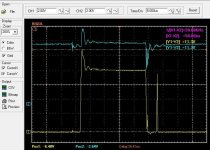
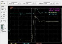
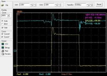
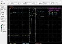
Your motor is a big inductor. To operate this motor, current is switched through these coils of the motor. Everytime the FETs switch from ON to OFF, the inductor trys to maintain this current level it was previously seeing (and the energy they use to do this is energy stored in building the magnetic field and the associated delay in the rate current climbs when initially switched "ON", so energy in/out is balanced). It can't maintain current by holding the same voltage, so as this field in the inductor colapses, the voltage skyrockets trying to maintain that current flow through the now greatly increased resistance of the FETs in the OFF state.

This effect is called flyback, freewheeling, or a number of other names to define this inherent voltage spike.

This flyback voltage spike occurs on absolutely every conductor that suddenly becomes an open circuit. If it's a giant coil of wire around a stator tooth, or a 2cm trace on a PCB, it has inductance, and when it switches from carrying current to not carrying current, it will have a spike. The magnitude and energy in this spike depends on the inductance of the path this current is/was flowing through.

To make an metaphor for help folks visualize this effect, think of the inductance in the system like a bungee-cord. As you the FETs switch ON at the start of a cycle, it tugs that bungee cord to a given stretch distance, and as the PWM cycles, it's moving back and forth, but the displacement of the stretch in the bungee cord dampens this effect, and keeps the tension of what you're tugging against roughly flat. Now, when the FET opens, it's like somebody just snips the connection, and the cord "fly's back" in way where that tension (current) gets very quickly converted into high velocity (voltage), and the things on both ends of this lead had better be ready to absorb this extremely rapid conversion from nice smooth tension into snapping that energy stored from stretching that bungee (energy stored in creating the magnetic field).
if anyone wants to make a better example, please do, I will replace mine with it. I am not a poet.
Here is a scope shot of what Luke is talking about. I'm working on this right now. The spike is measured from drain to source on the low side fet and as It turns off the current has to flow to the hi side diodes. I added an ultra fast diode to the hi side which helped but I found playing with caps is the ticket. I just ordered some snubber caps and some low esr film caps in the 1-10uf range I think the ones that will work best will be the 3mohm 8uh caps I have coming but I ordered a few types to play around and see what works best for me. Updates coming soon. If I can tame this inductive spike then I can turn the low side off faster and this will mean less heat in the fets so then I can up the PWM. I am successful at 20khz pwm the fets do climb in temp quite a bit during a dyno run (mesure 50-60 deg C after) but they cool fast (which meens I can't tell what they actualy climb to) and it seems they live but when I upped the PWM to 30khz I had a pass through which I am sure is because the low side fets got to hot from switching times around 1us if I want more PWM I need faster fet transitions. I also got two temp sensor kits to watch fet temps on the go so I can shut down before its to late for now on.
These pics show the low side as the yellow trace and the transconductance times and the spike from drain to source and the blue line is the rail voltage on that same H bridge. The voltage mesurements are 10x (probe was on 10x) I use ultra scope so I can save my captured data to a flash drive then come home and look at it and save it to my computer so I can study it in the future. 4.3 ohm gate resistor causing 113volt drain to source with ~720ns switch time and 6.8 gate resistor causing 102v spike with ~1us switch time.
 

Attachments

  • 4.3 ohm gate R.JPG
    4.3 ohm gate R.JPG
    73.1 KB · Views: 2,826
  • 4.3 ohm gate r 2.JPG
    4.3 ohm gate r 2.JPG
    70.8 KB · Views: 2,826
  • 6.8 ohm gate.JPG
    6.8 ohm gate.JPG
    68.8 KB · Views: 2,826
  • 6.8 ohm gate 2.JPG
    6.8 ohm gate 2.JPG
    69.9 KB · Views: 2,826
Great scope shots. So it looks like you're getting spikes that go about 20% above the supply voltage. We should keep this in mind when choosing FETs for a particular application.
 
fechter said:
Great scope shots. So it looks like you're getting spikes that go about 20% above the supply voltage. We should keep this in mind when choosing FETs for a particular application.
Yes and or the voltage you run them at. I can't wait to scope one of my China controllers to see how much the spike is. The scope shots I just posted was with fully charged 20s Lipo and 300 phase amps.
 
And your mission arlo to run 30khz PWM in order to push more phase current in a more controlled manner ?
 
scriewy said:
And your mission arlo to run 30khz PWM in order to push more phase current in a more controlled manner ?
I don't know the PWM I need yet... But yes higher is better with a low inductance motor but the analog design needs to be up to the task of switching that fast while producing low losses.!
 
Metal polypropylene caps are the best for what you want and they use short legs and the inherent design is low resistance and inductance. But the more important part is they are rated for hi ripple current which is what you actually need.
 
Futterama said:
Arlo, please give a link.

I was actually having aluminium electrolytic in mind when I asked. But you did not answer my question though.
I edited the post to say the right thing lol.

Here this is the caps I ordered. Find something like this. There is a few like this you can choose from.
 
Arlo, the voltage rating on those film capacitors are a bit off for my application which is 42V.

Still, no answer to whether ESR and impedance is the same thing, but apparently not according to my findings on Google. So what to do when digikey/manufacturers only give impedance and not ESR? Should capacitors without ESR data not be used as controller input capacitors?
 
Futterama said:
Arlo, the voltage rating on those film capacitors are a bit off for my application which is 42V.

Still, no answer to whether ESR and impedance is the same thing, but apparently not according to my findings on Google. So what to do when digikey/manufacturers only give impedance and not ESR? Should capacitors without ESR data not be used as controller input capacitors?
Yes but just find metal polypropylene caps that work its ok if the voltage is a lot above what you need. They have low ESR and ESL but as highhopes pointed out that's not what he looks for just takes note of the ESR/ESL numbers.
 
Futterama said:
A small question when looking for low ESR caps. When searching Digikey, many caps don't have an ESR rating, but they do have an impedance rating. Are those the same thing? ESR = impedance?

For our purposes, these would be basically the same thing. Lower is better. Yes, many of the parts won't have a ESR rating that indicates how well it will perform in a controller application. In general, metal film and MLCC types will survive high ripple current.

I have seen aluminum electrolytics overheat and explode if given too much ripple current.
 
CReeeek, thats the sound of the coffin door opening on this thread lol


Would this be a suitable cap to place in parallel with a couple of extra 50V-1000uF electrolytics on my Castle HV160? https://www.digikey.ca/scripts/DkSearch/dksus.dll?Detail&itemSeq=237009909&uq=636395606626940363

Meets the low ESR requirement, voltage spec running 14S battery..... although the capacitance is low, but what I gather it is total capacitance is not really key.

Thanks.
 
Back
Top