Yet another BMS

smartbms

10 µW
Joined
Oct 22, 2013
Messages
6
Location
West South of France
Hi,

First at all, i'm a newbee, and you're reading my first post on this forum.
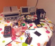
One year ago, i start develop a smart bms to finalize DIY ebike. Here a photo of :


Main characteristics :
- 8S cells frontend based on ISL94203 IC,
- powerfull low power STM32L103 MCU,
- 8 x 14 segments LCD display,
- 3 axis accelerometer to wakeup the pack,
- USB interface, for firmware upgrade and communication,
- small size 100x60mm, able to handle 30A, cell balancing, etc...

The hardware developping phase was a real pleasure, time to do some firmware : I started it with Chibios RTOS under a free of charge toolchain (Code Sourcery Lite / Eclipse CDT / GDB + STLINK probe) and with a lot of features in mind. I do made these items working :
- USB CDC serial support
- Command interpreter to read/write ISL94203 registers
- LCD driver (Chibios do not have it)
This was enough to debug my hardware and relauch a small batch of pcb (fully debugged ?)

I would continue on these software items :
- Low/high speed oscillator commutation if USB or not
- DFU bootloader on USB (to upgrade firmware in the field)
- Couloumb counting for fuel gauging (at 30Hz)
- Data logging (at very low rate, some statistics..)
- Cell impedance individual calculation during heavy loads
- DFU bootloader on USB (to upgrade firmware in the field...)
- etc

but to be frankly, firmware is not my cup of tea...

So, if somebody love STM32 MCU development under Linux with GCC rather soldering fine pitch SMT in his garage... let me know by PM.
 
Hi agniusm,

Onboard LCD allow to display some parameters of the battery without external computer (voltage including individual cell, current, watts, remaining capacity, alarm).
For example,it can do the job of a "Cy_leA__lyst" (fill the empty spaces) and more, thus at very low power consumption, passive LCD is driven by the MCU.

Here a view of my debugging set (8S1P battery with 18650 cells for dev purpose only, debugging probe, external cells temperature sensor)
DSCF2655small.JPG
I do not have LCD soldered to access some signals of the board with an oscilloscope probe to output something, this is also done by the serial over USB terminal interface.
 
circuit said:
I like your choice of MCU and front end. This looks like a very good start, probably the best project that I've seen so far. I just hope it will move forward and gets some good firmware written.

Thanks for these words. One more thing, some features of the ISL94203 allow to cascade it one time. This hardware platform should be upgraded up to 16S.
 
smartbms said:
Hi agniusm,

Onboard LCD allow to display some parameters of the battery without external computer (voltage including individual cell, current, watts, remaining capacity, alarm).
For example,it can do the job of a "Cy_leA__lyst" (fill the empty spaces) and more, thus at very low power consumption, passive LCD is driven by the MCU.

so another BMS is everytime welcome...but what are the specs of your bms?
looks like starting the same as 100 others do and no one finished something what "we" all need/Want ;)

as i see, your bms is for 8 cells? That means i need 3 of them for my Bike in series? :p
each can handle 40amps? and i hope you know that a CYCLE ANALYST ( i filled the empty spaces, because i dont know whats wrong with your keyboard :p) is not only to display voltage and cut of at low voltage (like a bms)
 
Hi Merlin,

At this time, this small board is set to handle 30A (connectors, MOSFET, shunt, copper trace an thickness) and exist only is a 8S version.
This BMS is more a hardware platform development rather a "ready to integrate" BMS (low level firmware developper and low voltage ebike owner are welcome !)
About CA, i know it does not a BMS job. It was just an example. My hardware can partially do the same (but the speed sensor input ? okay, no odometer on it). But it can also play with Ohm's law and compute individual cell internal impedance for example. With this feature, you'll be aware you own a battery pack composed of well matching impedance cells ... or not. You should consider it like a BMS able to protect, fuel gauge and self diagnose a battery pack of up to 8 Li-ion cells at this time.

Other point, the front-end IC is featured to be easily cascaded 1 time only for a 16S BMS. 16S at 4.2V equal 67.2V, other wait to say it's a 100V design (ceramic capacitor voltage, MOSFET Vds). It's a new board and depending of the success of this first board, i'll go or not. But you should not expect more than 16S. About current, hard to said. Generaly speaking, 100V MOSFET have a worse Rds on (higher resistance) than my actual 60V, rated at 1.7 milliohms each. An if you put many MOSFET in parallel, you also put in parallel each gate capacitance. The whole became hard to drive, and increase dangerous ON to OFF transition time, in case of short circuit protection for example.

For a 24S design (150V design), you're between MOSFET and IGBT in term of technology, but with the worst of it because at the end of the range.
 
Having more than 60V (16 LiFePO4 cells) on one board is a huge safety risk. If more than 16s is needed, do two separate BMS'es and link them together via isolated comm line.
I've seen some fires do to many small gauge wires with high potential differences going into one place. Orion BMS (very expensive) is a good example of really bad solution.
 
Hi smartbms.

Can you please tell what is your motivation to make this project and sharing the pictures on this forum? Are you looking to earn money selling it? what are your plans?

As for the BMS, I would go without LCD but put some kind of communication to outside like something 2 wire or wireless - so the BMS would be smaller. I think an LCD/Display would used on the handlebar (like on electric motor bikes and cars, even cycle analyts).
 
Hi casainho,

My motivations ? Finish this project and share different skills with other enthusiastics (someone which prefer GCC rather soldering a 0.4mm QFN SMD)
Do you know s.m.a.r.t for HDD drives ? I want to do the same for DIY batteries, detect bad cells as bad sectors. That's why i disclose my design on this forum.

Earning money selling it ? I have a job to pay my bills and my expensives hobbies spending. I'll be crazy to imagine having one day a money return on all i have already spend. But let imagine that one day this BMS concept and design become a successfull standard, i'm convinced that some people will take the opportinity to produce the board with or without my agreement. I like prototyping in my garage. On that way I'm ready to produce several boards at fair price (raw material + shipping) for some enthusiastics developers and give for free the actual SDK. When this design will be OK (and my relationship with developers), we will decide what to do of this project.

About removing LCD and reducing the board size ? 30A continuously in a pair of shunt and two big mosfet in series produce some heat. So downsizing the design is not so easy and need at least some calculation.

It's rather time to produce cool features and nice, well documented code developed on this existing hardware platform.
At this time, I'm the architect of this BMS (and the monarch :)) so no change on it !
 
I wish i could have skills to help you out developing this but, unlucky me i don't. If i wouldn't be out of place here, i would like to suggest implementing hardware needed for speed sensing. I know it is little related to the BMS stuff but you already have an LCD on it, so why not detach it from the board, make little more room on it and make it external to display all the stuff CA does or at leas stuff that each mortal would benefit from? This would make a huge difference in integrity. Now you need a bunch of additional wiring, external shunts and it is a pain, plain mess. If we could have a display for speed, range, battery level and as you mentioned before cell diagnostic and error reporting on the fly, that would be a winner.
Another thing is, why not get rid of discharge FET's and implement some kind of throttle cut off /throttle limit or similar? Anyway i envy people like yourself :oops:
 
whatever it needs....
6-8-12 cell bms we have enough....
what we need is 20-24-30s BMS using Lipos.
with 120/150 currents...

theres not the prob about the price....the prob is u cant buy it.
i havent any skills ins this way...but dont tell me it is not possible building a 24S BMS that can handle 150Amps....

:mrgreen:

so build it...i will pay 300$ :p
 
smartbms,

I prefer to code firmware than designing hardware. I wish I could find someone motivated to do hardware design on the motor controller project I started and on the BMS project. I started to document the projects on a wiki hosted on a free website host, which later the website were removed and I lost all the documentation - I didn't make a backup due to lack of time :-(
Here the last video I recorded about the controller (using STM32F100):
[youtube]I449L6JZkV0[/youtube]

About your project, did you thought in using Kickstarter/crowdfunding to produce a batch of boards? how much are you willing to invest on this project?

Right now I am a partner of a hardware/firmware/software company and I have no free time, however, I would love to "hack" on this project but only if it is suitable for me - my bicycle runs at 48V, the BMS I need must be to 48V. BUT MOST important, the project must be OpenSource - with adequate OpenSource license for the schematic/board source files, firmware and documentation.

A picture of my cheap chinese tools: oscilloscope; hot air station; power supply:
 

Attachments

  • bancada_electronica-2014.03.02.jpg
    bancada_electronica-2014.03.02.jpg
    143.8 KB · Views: 3,217
="smartbms"
Main characteristics :
- 8S cells frontend based on ISL94203 IC,
- powerfull low power STM32L103 MCU,
...
- small size 100x60mm, able to handle 30A, cell balancing, etc...
...
- Couloumb counting for fuel gauging (at 30Hz)
- Data logging (at very low rate, some statistics..)
- Cell impedance individual calculation during heavy loads

Hello,
I'm not in EV but I'd like to use the ISL94203 in home energy storage.
Do you have spare boards that I can buy to test the IC?
Thank you.
 
What scares me is that lithium battery industry is developing so quickly, that chip manufacturers hardly can keep up. This year alone there are over 20 new chips available. Sadly a lot of previously (1-3 years ago) announced chips are already obsolete (maxim & intersil, I'm looking at you). That is a bad business practice... Let's say I invest my time and money in to developing a BMS based on a chip, do tests, certification, preparation for mass production, etc... And bam, obsolete even before sales begins...
 
What is the power consumption in standby mode? Is it drawn from across all the cells equally?

The link to source materials doesn't work at the moment (goes to a holding page) or I would look at the design and figure it out myself.
 
dmwahl said:
What is the power consumption in standby mode? Is it drawn from across all the cells equally?

The link to source materials doesn't work at the moment (goes to a holding page) or I would look at the design and figure it out myself.

Datasheet claims 1uA from Vbatt, 50uA from Vdd in sleep mode, 1uA (by cell) from Vcell and another uA leakage (by cell) from balance pin.
It seems it draws current uniformally from the battery pack, not just one or two cells.
*Theorycally*, a pretty good IC, I'd like to test it, but Intersil has no stock for its eval board.
 

Attachments

  • ISL94203.pdf
    1.6 MB · Views: 228
manu12 said:
dmwahl said:
What is the power consumption in standby mode? Is it drawn from across all the cells equally?

The link to source materials doesn't work at the moment (goes to a holding page) or I would look at the design and figure it out myself.

Datasheet claims 1uA from Vbatt, 50uA from Vdd in sleep mode, 1uA (by cell) from Vcell and another uA leakage (by cell) from balance pin.
It seems it draws current uniformally from the battery pack, not just one or two cells.
*Theorycally*, a pretty good IC, I'd like to test it, but Intersil has no stock for its eval board.

Datasheet claims are one thing, real world numbers are another. I was hoping for some info on the whole system. Thanks for the link though, I'm going to read through it. Seems like a pretty interesting part, especially the standalone operation mode.
 
smartbms said:
One year ago, i start develop a smart bms to finalize DIY ebike.

Main characteristics :
- 8S cells frontend based on ISL94203 IC,

Hello,
Do you have spare boards to sell in order to check the ISL94203 functions (I've already send you a PM with the details)?
Thanks,
 
This is a great project. I wast thinking I'm the only one working with ISL94203.
My project is for my offgrid house and it suports up to 40A charge and 80A discharge.
I even had a small kickstarter campaign for this project search for Solar BMS or SBMS4080 if curios.
It is open source. I just released the hardware files and the software will also be soon released I need to make some changes since I changed the microcontroller to STM32F072 from STM32F051 there are a few pins difrences a bit more flash and RAM that I will probably need for uSD in the future.
 
electrodacus said:
My project is for my offgrid house and it suports up to 40A charge and 80A discharge.
Nice one!
Did you had thermal issues to design the pcb? (80A is quite big for a copper traces)
I wanna try to limit the output power to keep the design not too big, but it seems to be difficult.
Another problem I have is to get the State of Charge of the batteries. Have you try to implement it? If yes, do you use a dedicated chip for that or do you process it by integrating the current (Coulomb' counter) in the microcontroller.
 
Apart from an lcd display, my $25 board does all this.

Pc interface
5 led power level
out of balance threshold settings that you could calculate IR from, but there is no point.
8s (5-13 in fact)
30A (40A in fact)
Similar size at 120x50mm

It is also called the smart bms.

It also monitors a number of temperatures and can either flag faults or react with restarts or shutdowns.

I think a little light to tell me I should plug in the laptop is ample. More than enough. Few commercial designs give any advanced warning


If you can switch to a high power design, perhaps by cascading my bms which is known to be possible, then more help would come forward. People really want more power not more flashing lights.

Couple of my $20 boards cascaded to give 26s and fitted with better output components could be quick and cheap and wanted.

It is a shame to see people designing stuff we already have, and not finishing it. Adding screens seems a popular theme in these threads. While people are asking for more power.

My boards are still not ideal, as they are built for a certain cell count. If you want to change the number of cells, you have to alter the software and do some soldering.
 
Back
Top