Hrm, I'm not sure this mod works unless you have the adjustment pots.
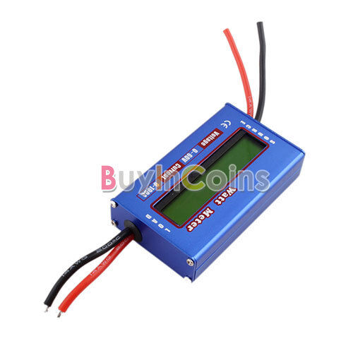
I just got a super cheapie watt meter like this one:
Which has no adjustment pots. I removed the shunt resistors (had 3 0.003 mohm resistors), and did the mod and wired it all up with 3-4 feet of 16ga wire. Tested with a 18w bulb. No amps. Hrm...double-checked the external shunt soldering, no shorts. So I tried it on a 500w motor on the stand, and it peaks out at 2A...should peak out at more like 5-6A.
I put the shunt resistors back in the original spots and it reads 5-6A again.
My guess is that the resistance of the sense wires is dropping both source/load voltages, causing a reduction in the perceived voltage drop across the shunt...if I had those adjustment pots i could tweak it back.
Thought I'd post in case it saves anyone any hassles.
Maybe I'm on crack and something else is wrong, but my guess is watt meters like this one with no adjustment pots can't do the external shunt mod...

")