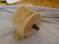
Kona Stinky, no pedals, big block on swingarm.

Drum

100 W
Joined
Dec 29, 2013
Messages
258
Location
Otaki New Zealand
Hi all,
I am new to the world of EVs, although I have had a general interest in them for a long time.
In December I decided to make an electric minibike for my 3 year old grandson, and it worked so well that I decided that grandfathers should be allowed to have a bit of fun as well, and that I should build something for myself.

I discovered ES and have been lurking for a few months, reading lots and learning fast.
The amount and quality of information here is amazing, and I would like to thank everyone for their time in sharing their knowledge and experiences with the rest of us.

I started collecting parts to add to my existing collection of mountainbike parts left over from other builds, intending to build an electric trials bike, patterned on the Oset 20 but slightly larger, but also had a few other ideas ticking away...

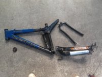
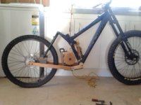
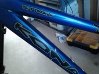
One day, a small size Kona Stinky frame came up on Trade Me (New Zealand's equivalent to Ebay) with a damaged swing arm pivot, and that aligned with one of the other projects I was considering, so I put a low autobid on it, and ended up getting it for $21!
Soon after, I also scored a strong 24 inch back wheel at a good price, so the electric trials bike has been put on the back burner and a new project was born:

I had been studying the Oset 20, and was impressed by the simplicity of the drive system. With the motor mounted on the swingarm and a fixed drive ratio, there is very little to go wrong, and components can be chosen to be strong enough to handle quite a powerful motor.

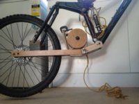
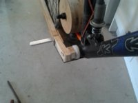
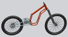
The basic idea is to build a complete new swingarm for the Kona frame and pivot it on a shaft passing through the bottom bracket position of the frame. At the back of the swingarm would be holes to take a 12mm through axle for the hub of the 24" wheel, and in front of the wheel would be a platform or other mounting for the motor.

The motor would drive the back wheel through chain drive of a fixed ratio. If the motor spun too fast for a single reduction (e.g. GNG or the similar "big block" motor), then a double reduction would be needed, but Ideally I would find a low revving, torquey motor capable of driving the back wheel through a single reduction of chain. I am currently favouring the lower kV 48V, 1000W nominal "big block alternative" motor starting to be discussed in other threads under the "mid drive" topic. This would have a single reduction of DID 219 chain, say 15 tooth driver and 77 tooth driven sprockets as a starting point.

The swingarm would have brackets on top to take the standard Kona back suspension system, although the longer swingarm would require a stronger spring on the shock.

With no pedals, and using the bottom bracket as the swingarm pivot, I would have to find another place to mount the footpegs. My current plan is to weld footpeg pivot brackets to either side of the swingarm between 10 and 20% of the swingarm's length behind the bottom bracket. This would mean that the footpegs move up and down a bit as the back suspension works, but I think that as long as they were not too far back, this would be acceptable.

As with any project, each decision involves compromises, and each advantage may be partially offset by a corresponding disadvantage. In this project, the main disadvantage I see is the need for a significantly longer swingarm (it is looking like the back wheel will be 100 - 125mm further back than with the standard swingarm). This will load up the back suspension more, and the bike would probably be harder to ride around really tight hairpin corners on steep singletrack trails. On the other hand it would help keep the front wheel down under hard acceleration...
There will also be significantly more unsprung weight, but the motor will be as close to the forward pivot of the swingarm as possible, so it shouldn't be too bad.

Then probably add a fixed elongated seat rather than a saddle, partly as a safeguard against falling onto the back wheel if a foot slips of the footpeg..

It is starting to sound a bit more like an electric motorbike rather than an electric bicycle, but as most of the components would be bicycle based, and other "no pedal" bikes have been included in this forum I feel ok to post here.

I will try to figure out how to post drawings and photos, and post more information soon. Meantime, any comments are welcome.

Regards,
Dave.
 
Great, I'm with you. I'm something equal.

77T/15T is 5.13 reduction. this will give you very low top speed or very high voltage. For 50kph you need around 440rpm at the wheel. So motor speed is 2257rpm. You need a voltage of around 88V or 24s Lion.

About the swing arm mounted motor, here is a cross reference http://www.endless-sphere.com/forums/viewtopic.php?f=2&t=50973
 
is is what i modeled yet, maybe useful
file.php
 

Attachments

  • swing_arm_big_block.png
    swing_arm_big_block.png
    58.2 KB · Views: 2,331
Hey Guys,
Great Idea / design on your Stinky 8)
Need something to be verified as I'm playing with a Big Block ATM as well.

crossbreak said:
For 50kph you need around 440rpm at the wheel. So motor speed is 2257rpm. You need a voltage of around 88V or 24s Lion.

I ordered this same motor that he has drawn in his illustrated idea above. Haven't checked the KV yet and its currently disassembled.
Crossbreak claims a KV of about 34 or so, which I don't doubt, but FYI, Mike from Lightning Rods has a "more GNG" looking Big Block
he tested to have a KV of almost twice as fast.
Just saying, they can differ and gearing is critical...

Good luck with your build!

Kevin
 
Hi Kevin,

good point, KV is indeed critical. You talk of the original BigBlock, we talk about the BigBlockAlternative. Both motors are about the same size, but different internally. The Alternative has 12poles and thus it spins slower.

Anyway i would be glad if someone could acknowledge my 34KV figure.

@Drum: Any decision about battery voltage yet? I like the idea of mounting the Pegs on that swing arm. You could then use the Bottom bracket as pivot. It's wider than the original pivot, making your swing arm more simple + maybe stiffer. Can you post a pic of your frame please?

$21 is a steal :D I just payed 45€ for a 2005 ghost frame with 150mm travel... it was only so cheap since it was painted poorly.
 
Hi Crossbreak, Thanks for the replies.
I have just re-read the thread on these motors and seen the low kV figure.. yes, 5:1 would be too much reduction. Hopefully someone else will have one of these motors running in a bike soon and can report actual figures.

I like your swingarm design. I had considered a similar one, but have decided the first one will be simpler / quicker to build, and will be making it from 40 x 20 x 1.5mm stainless steel box section. Once the bike is running, and the geometry is confirmed as correct, I could build a lighter triangulated one.
One of the reasons I chose a Kona Stinky is because the suspension forces are taken out at the back of the swingarm, so there is less bending strength or torsional stiffness needed in the swingarm itself, so the simpler swingarm construction will probably work ok.

Photos coming soon: Stinky frame as purchased, stripped, and built up with the forks and front wheel, with a "full scale model" of the motor made of wood, sitting on a full scale adjustable model of a swingarm.

I envy those of you who are skilled in CAD, it must make it much easier to decide whether a design will work, but I did my engineering training before CAD existed, and have always been too busy to learn. So I do full size sketches and make full size models to verify before starting to build.. works ok.

Voltage, batteries, controller, throttle etc still undecided. I had thought 60V, Lyen controller connected to Version 3 Cycle Analyst, and the best throttle I can find. However I am seeing comments about "torque" throttle control as opposed to "Speed" control, so I realise I still have a lot to learn!
It is important to me that I have smooth throttle control as a lot of the soil in my area is hard clay which becomes very slippery when wet, so fine throttle control helps a lot!
Advice on controller / throttle welcomed!
 
if you need a smooth throttle, i think you should go for Sabvoton or Kelly. Personally i like the Kellys more for their smaller Package and more precise Specs. Lyen will allways have a strange throttle behavior, unless you use a very sophisticated throttle mapper.

Yep, designing a swing arm for the stinky will be quite easy, i'm keen for pics. I'll try my BigBlockAlt with 14/54T with T8F chain as soon as i have time for that. All i need are front wheel, a fork, rear rim and a motor mount. Everything else (controller EB312, motor, battery 74V 20s Lipo, hub Shimano FH-M525A, frame, gears etc) is waitng already in a box :D
 
nice! using the BB as pivot makes sense. you coult use HT2 bearings and a 24mm shaft ....what do you think?

this would widen your bearings... i dont know how wide your original ones are.. you would get a width of 100mm or so with the HT2 bearings... does this make sense to you? My aim is to keep the swing arm as "straight" as possible... it does not have to get narrow at the pivot anymore... this swing arm in my CAD pic is completely straigt.
 
Here's a few photos showing where I have got to so far.

The wooden "geometry testing" swingarm is NOT the final shape I hope to use, but was made with the right angle at the front for simplicity in testing. Hopefully the front can be sloped up to meet the bottom bracket of the frame so there is no corner to get hooked on logs / rocks as I slide across!
 

Attachments

  • 2014-03-26 09.44.40.jpg
    2014-03-26 09.44.40.jpg
    37.2 KB · Views: 7,390
  • 2014-03-26 09.40.48.jpg
    2014-03-26 09.40.48.jpg
    46.1 KB · Views: 7,390
As can be clearly seen on Crossbreak's CAD drawing a few posts ago, the mounting feet of the motor are the limiting factor in how far forward the back wheel can be mounted, therefore how short the swingarm can be.
In my case, with the backwards - sloping seat tube of the Kona frame, I have to mount the motor lower or further back to allow for the upwards / forwards swing of the motor as the suspension compresses. This means that the front edge of the motor feet also define the furthest forward point of the "low part" of the swingarm, and therefore the "least ground clearance" point of the whole bike.

Two possibilities I can think of:
1) Cut off the motor feet entirely and mount the motor on "ring plates" similar to the GNG setup, picking up each end of the four bolts that hold the motor together; or
2) Rotate the motor so the feet are more - or - less vertical and bolt the motor to a plate that is pivoted low in the swingarm just in front of the back wheel. Tensioning the chain would be by swinging this pivoted plate forwards / backwards.

I think option 1 might be the better in engineering terms, but option 2 at least leaves the motor in original condition and could be done easily. I had always intended that there would be a "mudguard" of some sort between the back wheel and the motor to keep the motor clean in muddy conditions. This vertical plate would provide easy mounting for the mudguard, so I think that is the way I will go.
The swingarm could slope up towards the frame's bottom bracket from just in front of the pivot for the mounting plate, improving ground clearance also.
 

Attachments

  • 2014-03-26 10.10.37.jpg
    2014-03-26 10.10.37.jpg
    43.9 KB · Views: 7,373
  • 2014-03-26 10.16.48.jpg
    2014-03-26 10.16.48.jpg
    47.4 KB · Views: 7,373
OK, Mark 2 swingarm, with the motor mounted to a hinged plate.

Unfortunately, rotating the motor so the mounting feet are vertical has increased the height of the motor above the bottom of the swingarm, meaning it has to move back slightly to miss the seat tube when the shock is fully compressed.
This means I did not gain anything in terms of how short the swingarm can be, but I gained greatly in ground clearance and shape at the front of the swingarm.

Looking ok.. might be time to order my motor etc!
Any suggestions on possible suppliers at best price? I am in New Zealand, so probably suppliers in Asia make sense, rather than Europe.
 

Attachments

  • 2014-03-26 12.45.46.jpg
    2014-03-26 12.45.46.jpg
    53.3 KB · Views: 7,359
  • 2014-03-26 12.43.53.jpg
    2014-03-26 12.43.53.jpg
    51.9 KB · Views: 7,359
Hey Drum,

The link that BZH originally posted http://e-bike-diffusion.com/index.php?module=produit&prd_id=509&url_retour=http%253A%252F%252Fe-bike-diffusion.com%253A80%252Findex.php%253Fmodule%253Dcategorie%2526code_cat%253D24%2526page_start_num%253D1
Is where I ordered mine... pretty sure this is Crossbreak's source as well.
I'm in the USA, so not a perfect reference but shipping was reasonable, and fast. It was packed very well too,
comparing other "heavier" items I've received from Asia.

Loving your wood mock-up.. I need to keep this method in mind more as my experience there is more significant
than metal work. And better than my CAD efforts (cardboard aided design) :lol:

Looking good!
 
Hi K-ray,
Thanks for that. It is sometimes worth paying more to deal with a "known" supplier who has done their job well in the past, and it seems that this supplier has done ok for more than one of you..

The cheapest I have found is this: http://www.mistertao.com/beta/pages/item/36266184609.html but of course there is Mr Tao's added commission and the fun of dealing with a lesser - known supplier in China.

My guess is that YK Success are the manufacturer of the motor, and that BHT buy from them and re-sell with their own badge and a sprocket.

The motor is also available direct from YK Success's own website, but without the protection of an English speaking agent like Mr Tao or Easy Taobao I would be doubtful that communications would be perfect and shipping cheap.
 
Hi Crossbreak, to answer a couple of questions you asked earlier:

nice! using the BB as pivot makes sense. you coult use HT2 bearings and a 24mm shaft ....what do you think?

this would widen your bearings... i dont know how wide your original ones are.. you would get a width of 100mm or so with the HT2 bearings... does this make sense to you? My aim is to keep the swing arm as "straight" as possible... it does not have to get narrow at the pivot anymore... this swing arm in my CAD pic is completely straigt.


Yes, I intend to use an external bearing bottom bracket (or slightly modified version) as the swingarm pivot.
See photos below:
Bottom bracket width:
This is my daughter's mountainbike with external bearing bottom bracket. It has a 73mm width at the frame and no spacers inside either bearing housing. Most of my other bikes with external brng BBs are 68mm frame width with spacers to bring the overall width to the same figure, just under 100mm. Without stripping and measuring each of them I cannot be certain how much variation there is, but if you allowed 100mm or just above at the inside of the swingarm, a couple of shim washers would sort it out quickly.
Bearings:
The external bearing BBs I have played with all use the same bearings, type # 6805, 37mm OD, 25mm ID, 6mm wide. They are available in Ceramic as well as steel if you are rich.
The Shimano cranksets use the full 25mm bore on one side and are bushed down to 24mm on the other side. Either size could be used for the swingarm pivot shaft, or indeed any smaller size, with appropriate bushes.
Alternatively a more common, cheaper and stronger bearing could be adapted to fit, using a smaller shaft, but that would increase the width at the outside of the bearing.

Swing arm width:
The wooden mock-up swingarms I have made are parallel, constant width right along. The gap between the arms is 140mm, and with the width of the box section being 20mm, this gives 180mm width outside.
The front of the swingarm looks wide compared to the slim main frame loop, but for the first "real" swingarm I intend to keep the sides parallel.
My only worry is whether there is enough room to fit the motor in a position where the sprocket is close enough to the centre of the swingarm for the chain to pass inside the suspension link and meet with a sensible position for the sprocket at the wheel. If this is a problem, I might have to widen the swingarm or raise the motor further so the body of the motor sits above the swingarm at all positions of chain tensioning. Even in the earlier photo it is high enough to allow the back of the body of the motor to overhang the swingarm box section and still be adjusted quite a bit.
 

Attachments

  • 2014-03-26 14.35.58.jpg
    2014-03-26 14.35.58.jpg
    65.6 KB · Views: 7,343
  • 2014-03-26 14.48.52.jpg
    2014-03-26 14.48.52.jpg
    23.6 KB · Views: 7,343
  • 2014-03-26 14.44.12.jpg
    2014-03-26 14.44.12.jpg
    40 KB · Views: 7,343
Things look nice. Isn't that a coiler not a stinky? I can't read the writing, but been looking at Konas and the stinky has the rear shock at an angle, whereas the coiler has it up and down against the tube. Of course some local had a stinkin' Coiler up for sale with the rear triangle of the stinky and a Coiler frame. I do wonder about your peg placement though. It looks like you'll have to be careful about getting feet/pants wrapped in the chain and sprocket.
 
Hi Dirkdiggler,

Its definitely a Stinky, but an early one. The previous owner said it was a 2003 model... I don't know if that is correct, but they did change a bit over the years so the more recent ones do look a bit different.

Yes, it will need a guard over the sprocket.. I don't fancy the thought of several kW of grunt engaging in an attempt to swallow my jeans while my leg is inside them!
 

Attachments

  • 2014-03-26 17.29.04.jpg
    2014-03-26 17.29.04.jpg
    56.6 KB · Views: 7,327
if you raise the motor you will again get clearance issues with the seat tube i guess.
with a straight swing arm you shouldn't get clearance issues with the chain :? since it's straight.. maybe you have to make a new suspension links as well to get this issue solved?

You can play around with chain line since you got plenty of room on the hub if you use a cassette freewheel hub with lots of spacers on it. I tried that with my 135mm dropout frame, seems to fit fine with the motor centered almost.

, I might have to widen the swingarm or raise the motor further so the body of the motor sits above the swingarm at all positions of chain tensioning.
so you wanna move the motor for tensioning?

BTW there are T8F sprockets available with 35mm ID so you can simply bolt it on some worn sprockets of an old cassette (my plan as well) and simply lock the freewheel with balls like shown in the LMX P2 thread http://endless-sphere.com/forums/viewtopic.php?f=28&t=57668&start=25#p867688 but bzhwindtalker told that #219 is superior to T8F chains.
 
Yes, I intend to move the motor for chain tensioning, Either the motor or the wheel has to move, and the chain puts equal and opposite forces on them. However, the back wheel also takes the weight, traction and braking forces, so I am going to simply drill 12mm holes accurately opposite each other for the 12mm through axle of the back wheel so it cannot go out of alignment (unless the swingarm bends) and moving the motor for tensioning. At least with the motor you only have to cope with force in one direction.

As I have lathes, milling machine, TIG, MIG, arc and gas welders etc, modifying sprockets is not a problem. I had decided to use 219 chain because of the large range and cheap price of sprockets available from the Karting supplies shops, and its proven ability to handle horsepower. There are two local sprocket manufacturers in my area if I want something weird made, so not too worried about sprockets yet.

Good to hear that you think it will work within the width of a standard rear hub.

I think that the major decision is whether to put both the rear wheel sprocket and the disc on the left of the hub using the 6 bolt flange, or lock the freewheel in a strong way to take both drive forces and regen braking forces and keep the sprocket on the right. I would rather keep the sprocket on the right if I can lock the freewheel solidly enough, so keeping chain oil away from the disc and simplifying things generally.

Some of the engineering metal-filled epoxies are amazingly strong.. it is possible that simply filling up the freewheel ratchet area with epoxy and holding it in the engaged position while the epoxy sets may be enough.. the combination of the standard pawls and the epoxy in the drive direction, and the epoxy by itself in the regen direction.
Trouble with ideas like that is that you usually find out it wasn't really strong enough when you are 30km from home and darkness is falling!

Possibly I could machine 3 or 4 matching keyways in both the hub and freewheel and press them together with epoxy as well. I haven't stripped the hub yet to see what could be done. Things like that canl be done while I wait for the motor to arrive.
 
yep, i think moving the motor is easier, too. It wont make any difference to the swingarm length if you move motor or wheel, the space required is the same.

why not just put in some metal pieces like shown in the picture and then fill up the rest with epoxy? should be rock solid!

Machining a spocket that fits the cassette spline exactly will be difficult, no matter how many mills you have at home. Lasercutting would be an option though. Still, why not simply use a body of some old cassette... can't see any flaw in that. You can still enlighten it somewhat on the lathe. I have a worn shimano XT-cassette with nice alloy body for exactly that purpose. My lathe is 100mm dia max, so i have to make an adapter anyway.

Good to hear that you think it will work within the width of a standard rear hub.
A 142mm one has wider distance spoke flanges...makes the wheel a lot stiffer. I just use 135mm since i have the parts laying around anyway. For a straight swing arm, 142mm fit's better, for the motor length as well.
 
My small lathe can swing a diameter of 255mm over the bed, and my big one can swing a 16 inch 4WD rim with room to spare, so I am not limited by size in terms of bicycle components!
Yes, I think using a worn out cassette in some way to mount the sprocket is the right way to go. If the sprocket is steel, it could be welded to the back of an old cassette and spaced to suit. If aluminium, it could be centered on the OD of the spline and bolted through the biggest sprocket of the old cassette... lots of options.

If I was starting out from scratch I would look for a wider back hub, but I already have the 135mm one. I will make the swingarm so it can take the wider one as well, and tack weld washers inside it so it is secure for the narrower one for now.

Good to see you have the components coming together for your build!
 
it could be centered on the OD of the spline and bolted through the biggest sprocket of the old cassette
That wont work. You can't turn around the spline. The old big sprocket must always be at the spokes. I'll have to get rig of the old sprockets. Welding worn steel sprockets to the new one indeed is something worth thinking about. You will need a lot old sprockets to get a stack that is around 10mm thick. Still more effort than just turn the old body down and use some bolts i think
 
Yes, but you don't have to use the whole width of the cassette. Most of my Shimano cassettes have the biggest few sprockets pinned or welded together, but the smallest 3 or 4 are loose, so by leaving the loose ones off, the pinned unit could be slid outwards and the sprocket connected to the back of the biggest one. This could then have a spacer to hold it out away from the hub to give clearance for the chain from the back tyre. Anyway, details like this get sorted quite easily.
Work has intruded over the last few days so no progress.. hope to move forward again in the weekend.
 
Back
Top