How far can you mod a 28mm (9C Clone) DD HUb?

40mph with the stock rim and spokes but after 4 months of riding the spokes are getting loose and the wheel untrue. Still runs smoothly at high speed but I will be switching to a crystalyte motor shortly.
 
evolutiongts said:
40mph with the stock rim and spokes but after 4 months of riding the spokes are getting loose .....

I don't go as fast, but I had a similar problem with my spokes getting loose after a period of riding....about 9 months. I tightened them once while truing the rim and haven't had a problem in about two years.

:D
 
Yeah, nothing actual bike maintenance wouldn't cure.

I was just telling another guy yesterday, you actually have to maintain a pre built ebike too. Bike maintenance is easy to learn, but people want it to happen in the background nowdays, like it's a computer software update.

What's needed is a good ebike man at the local bike shops. It doesn't help any that a bike shop often won't touch an ebike.
 
Maintenance is the only reason I recently found a broken spoke...LOL I like riding more than the maintenance, but it's part of a hardcore ebiker's life...LOl Hell bound for lithium....lol
 
teslanv said:
Yeah, I know the crowns and Cromotors are the kings right now hub wise. But being my first mod like this I thought it would be wise to "Practice" my craft work on something less valuable, and also a motor that won't be overkill on my current bike.

If you are going to go for it a couple of pointers from my upgrade go like this:
(no particular order.)

12awg, the kind that is used in house wiring is the easiest to use. It just won't handle all the amps you would like.

You can probably use 30awg sensor wires, but make sure the insulation is capable of handling the highest temperature possible.

Likewise for any shrink tubing you use inside of the hub. It needs to take the heat.
a lot of Very High Temperature, Heat Resistant & Thermal Insulating Fiberglass Sleeve is always a good choice.

If you can get 7 sensor wires through the axle then it will be easy to instal a temperature sensor of some sort.

Be very careful with the hall wires as the legs on the sensors can easily break off and then you will be replacing your hall sensors also.

Use your Dremmel tool to smooth all edges of the axle bore so you insulation doesn't get cut. No Dremmel tool? Looks like you will need elbow grease and a file.

That is all I can think of in the short time I have at the moment. Keep us up to date!

:D
 
I will redo the phase wiring on mine (actually a GM unit, but I figure they're all much the same) I think I shall go with:

Stripped 12awg wire in high-temp heatshrink

Fibreglass sleeve over the bundle (if it will fit!) for abrasion resistance

Hall wires are already 24 or 26 awg silicone, which was the thinnest I could readily source.
 
Here's my thoughts on phase wires. A chain will fail at its weakest link. The same goes for electrical wiring. So what good does it do to use 12awg phase wires if the motor coils are 14awg? All you really gain is less voltage loss between the controller and motor coils. There's a 2.1V drop in a 4' circuit (about the length of the stock phase wires from motor to controller at 40A) using 18awg wire. 16awg is 1.33V. 14awg is .83V. 12awg is .52V. Now just shorten the phase wires to a 2' circuit and the losses will be cut in half, so you can eliminate a lot more by just making the connection from the controller to motor shorter. Doubling the amperage will double the loss. Personally I'd rather burn up the phase wires than the motors coil wires. That's why I'm just going to shorten the stock phase wires just outside the motor and replace the rest to the controller with 10awg and shorten it to needed length, which is only about a foot in my case since my controller wires come out right at the BB. You can figure voltage losses with the calculator at the bottom of this link.
http://www.powerstream.com/Wire_Size.htm
 
wesnewell said:
Here's my thoughts on phase wires. A chain will fail at its weakest link. The same goes for electrical wiring. So what good does it do to use 12awg phase wires if the motor coils are 14awg? All you really gain is less voltage loss between the controller and motor coils. There's a 2.1V drop in a 4' circuit (about the length of the stock phase wires from motor to controller at 40A) using 18awg wire. 16awg is 1.33V. 14awg is .83V. 12awg is .52V. Now just shorten the phase wires to a 2' circuit and the losses will be cut in half, so you can eliminate a lot more by just making the connection from the controller to motor shorter. Doubling the amperage will double the loss. Personally I'd rather burn up the phase wires than the motors coil wires. That's why I'm just going to shorten the stock phase wires just outside the motor and replace the rest to the controller with 10awg and shorten it to needed length, which is only about a foot in my case since my controller wires come out right at the BB. You can figure voltage losses with the calculator at the bottom of this link.
http://www.powerstream.com/Wire_Size.htm
That's a convincing argument, wesnewell. Maybe, just upgrading the phase wires right out of the shaft would suffice?
 
wesnewell said:
........The same goes for electrical wiring. So what good does it do to use 12awg phase wires if the motor coils are 14awg? ......

14awg? On your 48v hubs? :shock:

Yea, I couldn't get a real since of just what I had when my 36v motor was open. I tried, but could not tell exactly how many strands of wire and what gauge the wire was....24 awg...26 awg? So I couldn't calculate an accurate total wire density and extrapolate an awg rating.

But, we are not talking voltage here so much as talking current (amps). I still think that if one wants to push max amps through a Yescomusa motor, a phase wire upgrade is in order. If 14awg is all that is needed, then a 12 awg THHN upgrade would be fine. A 12 awg pull through the axle isn't all that hard. A 14 awg THHN pull would be even easier.

Having done a solid wire upgrade, I recommend stranded over solid wire for better flexibility out of the axle, both sides.

:D
 
Here's my thoughts on phase wires...what good does it do to use 12awg phase wires if the motor coils are [the smaller] 14awg?

The enamel on the phase wires of the cheapest hub motors has taken 200F/93C and survived, but...enamel is brittle, so it is OK to use clear enamel on the non-moving stator. The phase wire insulation will chafe with even a small amount of heat expansion and cold contraction. Sometimes the hole openings at either end of the hollow axles is a little too sharp.

Also, the mass of the steel in the stator laminations can absorb "some" of the amp-spike heat peaks, the three phase wires struggle alone...For stock temps, the stock phase wires and insulation are OK.

Fatter wire runs cooler than thinner wire, teflon insulation is tougher and more heat-resistant than the stock insulation.
 
spinningmagnets said:
...... but...enamel is brittle, .....

Brittle? Please explain...I mean I can twist my motor (magnet) wire in a lot of different directions without the enamel breaking off....do you mean when it rubs together? I don't get what you mean...

coils.JPG

Thanks!

:D
 
I have measured 110c (230 degrees F) though the vent holes I drilled on my yescom motor back 4 years ago when I built my E-bike. I'm guessing it has been up to 120c (250F). The motor has around 700 miles on it now. I pretty much ride for fun with an occasional errand. I have not burned it up yet. It seems to be just as strong as it was new. Specs are below in my signature. I usually ride constants of 1000W-2800W. That's 20 to 43mph. I have short 10 to 20 second of 50-60amps (3500W-4000W) accelerating and accelerating up hills. From accelerating from a 3mph roll, I peak 110 amps (over 7000W) and my watt meter rolls over and resets most of the time. haha. I usually do this at least 1-2 times every time I ride. I am light at only 135Lb's, and the bike only weighs 75lb's. This can make a big difference in loads on the motor.

I do smell the varnish smell almost after every ride. I know this baby heats up and eventually it will fail but I don't care really, it was cheap. Again it seems to have the same power it used to have when I first got it. When it does go, I will most likey upgrade a crystalyte motor that already has larger gauge phase wires, and I will save all the mod time and drilling holes.

Here is a huge thread on cooling motors:
http://www.endless-sphere.com/forums/viewtopic.php?f=2&t=9791

I remember DoctorBass had a temperature alarm at 135c on his motor, that's 275 F.

I also used 12AWG PTFE covered wire, that is 0.11" diameter, handles 390F temps for the phase wires on my motor.
 
I meant that compared to Teflon insulation, the enamel on magnet wire would not survive living in the hollow axle of a hub motor. If anyone ever did use enameled magnet wire with no additional insulation inside the axle just to prove it was possible, I still wouldn't risk it, personally...
 
Punx0r said:
I've currently got a thermocouple wired in mine. Would a 10K NTC thermistor be better? I'm thinking compatibility with various off-the-shelf temperature displays.

It seems an LM35 sensor is the tool for the job:

http://endless-sphere.com/forums/viewtopic.php?f=2&t=56880
 
Finally picked up a couple 9C Clone DD hubs. Got a Yescomsua 48V 1000W Kit off ebay and also a Mxus XF40 (8.5kV) DD Hub. - The Mxus wheel is really nice with a Alex DM18 26" wheel & 12g spokes. - So I'll probably mod the Mxus, and throw the Yescomusa wheel on the wife's bike without mods.

As far as modding goes, I am going to install a NTC 10K Thermistor, and upgrade the phase wires to 12awg (PTFE high-temp, abrasion-resistant aircraft wire).

Also planning on coating the hub interior with insulating varnish.

Controller will be a 6-FET 4110 Lyen Mini Monster (25A) for the daily commute and swap it out with an 18FET 4110 Lyen (50A+) for high-speed fun on occasion.

Will I fry the 4110FET's if I run 24S (100.8V Max) on them?

I also want some advice on active cooling:

Assuming I don't upgrade the hall sensors, would I be better off to air-cool or oil-cool the motor? - I am a bit concerned that if I go with oil cooling, the movement of the oil inside the hub will want to pull the hall sensor wires out, under high-speed. - With air cooling, I wouldn't think this would be much of an issue. - Just wondering if anyone that has done the oil-bath cooling has had this issue?
 
Until you get oil-cooling fully sorted out, it can be messy. That being said, you can try oil-cooling first and then after you have collected several weeks of heat data over a variety of power levels...you can then clean everything out and try air-cooling.

From low amps up to the point where you reach saturation, each bump in the max amps you use will increase the acceleration, but...it will also increase the heat an equal amount. Just for the sake of argument, lets say a 10% bump in amps will give you a 10% bump in heat. All fine and good until you are putting in more heat than the hub can shed.

Then as your amps experiment reaches the saturation point...a 10% bump in amps will definitely give you a bump in power, but...the heat resulting will be much more than 10%. The heat will curve steeply up at that point in the graph.

This is further complicated by the fact that the "max amps" cap in the controller (or the Cycle analyst) may only be reached for a few seconds until the bike reaches it's top speed. Then...the amps slide back down to a lower level, just enough to maintain the load/cruise-speed. If you run 40A in a 28mm wide stator, you will be making crazy amounts of heat for a few seconds...then the amps slide down to 10A-20A...and it cools off...but slowly.

The danger is in a long uphill where the bike is drawing 30A-40A for an extended period, or you have a fast winding and you are going 40-MPH, which applies a LOT of wind resistance...forcing the controller to feed more amps than a normal cruise phase in order to keep up...

If you live where it's very flat, you can get away with giving one of these 9C clones a LOT of abuse...but put that same high-amp 9C system in an area with some hills, and when you loan the E-bike to a friend...he will be making the walk of shame back to the starting point and complaining to you about how bad the bike smells.

I like oil-cooling/air-cooling, but...they are just a bandage. If a temp sensor says the stator is getting too hot at "X" amps, get a motor with a wider stator. The Crystalyte H35 series has a 35mm wide stator, the 4060/4080 has a 40mm wide stator, and the Cro has a 50mm wide stator...
...or maybe a mid drive?
 
I pushed my 9C 2806 harder than most people have a 28mm stator, 58mph top speed on 125V. Trick is minimizing the load, small diameter tire, lower turn count (higher KV) so the saturation point is higher, and ventilating the motor. This motor still works great, windings look brand new and is now on my Wife's bike living a much calmer life.
[youtube]UOenEWOHcsk[/youtube]
 
zombiess said:
I pushed my 9C 2806 harder than most people have a 28mm stator, 58mph top speed on 125V. Trick is minimizing the load, small diameter tire, lower turn count (higher KV) so the saturation point is higher, and ventilating the motor. This motor still works great, windings look brand new and is now on my Wife's bike living a much calmer life.
What controller/Current are you running on that Video, zombiess?
 
I use magnet wire to get the maximum copper through hollow axles. I use 16awg magnet wire and solder the motor end of 3 sets and check for continuity of all conductors in each. I add the hall wires and 2 extra pairs for a temp sensor and a spare pair for future use with extra length of the smaller wires. I stagger the 3 interior ends of the phase wire bundles to make it easier to get through the bend at the inside end of the axle hole and wrap the entire bundle of loose wire tightly into a circular cross section using electrical tape with no overlapping. Over that goes 2 layers of properly sized heat shrink for 4 layers of electrical insulation, though the tape is more just to hold the bundle nicely for the shrink.

I prepare the axle hole with a small round file to remove sharp edges, and then after a dry test fit which involves bending the end to help it through the curve, I lubricate it with silicone. Getting the relatively stiff bundle through involves pushing from the outside end and pulling the inside end using a pair of pliers on the soldered end of the first phase wire.

This method fits more copper because 3 round individually insulated phase wires leave a lot of extra space in the circular hole. The insulating varnish is sufficient insulation between the phases just like it is inside the motor, though you don't want to bend and flex this type of stiff wiring harness much.

Having thick conductors isn't just about lower losses in the wiring. A larger gauge will sink more heat from that end of the motor windings resulting in a lower temperature inside the axle. I suspect that most hall failures are actually a failure in the wiring from having the hall wires in close proximate to hot phase wires. This deforms and partially melts the insulation on the hall wires, which make it brittle. Intermittent short occur which blow the halls. I believe that's why so many people have repeat hall failures.

The most involved part of the entire process is getting a half inch or so of the magnet wire enamel off the ends each conductor and solder one end and checking continuity of each conductor. I though I separate them physically with tape, I don't join the exterior end of the phase wire bundles until after the harness is installed, soldered to the phase wires, and again checked individually for a good connection inside the motor proven by testing from the outside.

Other mods:
If you're going to the trouble of improving a motor, you only want to do the job once, and you might as well do it right. For me that includes changing the bearings to good quality bearings whether the motor is new or not. The bearings they put in hubmotors typically vary from poor quality at the worst to average quality at best. Another mandatory thing for me is a rust prevention coating on the stator steel, for which I've used paint designed for inside motors as well as oil based rust proof coatings. Both have worked well, though I worry about paint getting scrapped off during reassembly as the stator rubs on the magnets on the way in. I do whatever little things I can think of, like extra zip ties to ensure wires are secure in the motor, and adding extra epoxy to halls or hall wires if they look like they need it.
 
For helping determine the voltage and current limits of the particular motor, start with the Kv, the no-load rpm per volt. Lower Kv motors can handle more voltage better, and higher Kv motors can handle more current better.
 
Latest plan is to ditch the temperature sensor and attach a thermal cutout to the laminations and use it to break the power connection to the hall sensors.

What sort of temperature cut out would be appropriate? I'm going to run oil cooling, so I guess this will result in a cooler stator and hotter magnets. The lowest grade of neodymium magnets are good for 100°C.

Also, is "thermal cut out" the correct term for the component I'm thinking of? You see them in all sorts of domestic appliances, but I'm getting few/no matches on ebay or with electronic component suppliers.
 
My Mods are progressing...

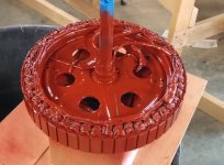
I have upgraded the Phase wires to 12AWG PTFE (Aircraft Grade) Wire, Added a Thermistor, and sprayed the stator & Rotor with Insulating Varnish.

Varnished stator.jpg

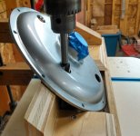
I decided to go with Air Cooling. I am going with a variation of the venting holes, with a bit of a twist as it were. I drilled the venting holes (5/8" DIAM done with a forstener Bit) at a 45 degree angle to the face of the Cover plate.

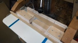
Here is the jig I cobbled together to hold the cover plates in position.

Drilling Jig.jpg

And here is the drill angle:

Mxus Venting Holes.jpg

My theory is that with a slight pitch to the holes, it will induce directional air flow (Like an impeller), with one side pulling air into the motor and the opposite side pushing air out of the motor. I suspect the effect will be subtle, and I would have no way to empirically test to see if it makes any more difference than just a straight-drilled hole. But I figured, why not.

Now I need a source for high-quality Bearings to swap out for the standard Chinese ones that came with the motor. - Any recommendations for bearing suppliers/manufacturers?
 
Back
Top