Cycle Analyst V3 preview and first beta release

esoria said:
Yes justin, this is my settings for 28S 8A Nanotech 25-50 Lipo from Hobbyking
I set CA for Lipo, 28S string, 8A capacity....
But if i remember i dont see in menu' "RClip" but only lipo!
there is nothing like rc-lipo. lipo is fine. and is Ah not A. A = current
 
Can someone explain what is meant by

If you have a way old unit with Beta15, then you will first need to use the “CalOverwrite” firmware option.

as instructed on the CA v3 page on the Grin website? How do I find out what version of the firmware my CA has currently? If I have Beta15 or older, what extra step do I need to perform to update that firmware?
 
onlineaddy said:
Can someone explain what is meant by
If you have a way old unit with Beta15, then you will first need to use the “CalOverwrite” firmware option.
as instructed on the CA v3 page on the Grin website? How do I find out what version of the firmware my CA has currently? If I have Beta15 or older, what extra step do I need to perform to update that firmware?
turn it on? it shows the firmware version for some seconds during boot. firmware update is described int the inofficial user guide posted by teklektik.
 
izeman said:
esoria said:
Yes justin, this is my settings for 28S 8A Nanotech 25-50 Lipo from Hobbyking
I set CA for Lipo, 28S string, 8A capacity....
But if i remember i dont see in menu' "RClip" but only lipo!
there is nothing like rc-lipo. lipo is fine. and is Ah not A. A = current

So if i set in CA "Lipo-28S-8Ah" i set all correct, but SOC gauge not working well
 
what voltage to you charge to? how do you know your soc? do you determine by voltage or ah used?
if it's voltage: what voltage would you expect to show as empty?
if it's ah: are you sure you set your shunt valur correctly? if set wrong it will show eg more ah left than there really are!
we need more data!!!
btw: i know that justin mentioned rc-lipo. justin: where do you set that? i can only see lipo.
 
I charge my 28S 8Ah lipo at 4.1 volts for cell
My shunt is perfectly calibrated
I know i empty the pack, because after 7Ah used my cutoff kick in and i read on CA 99.5V, so 3.55 volts for cell

After i use 7 Ah is impossible to see on the CA half full SOC gauge, i have to see flashing empty Gauge icon
 
esoria said:
I charge my 28S 8Ah lipo at 4.1 volts for cell
My shunt is perfectly calibrated
I know i empty the pack, because after 7Ah used my cutoff kick in and i read on CA 99.5V, so 3.55 volts for cell

After i use 7 Ah is impossible to see on the CA half full SOC gauge, i have to see flashing empty Gauge icon

You need a version of the CA firmware that includes the RCLiPo profile to apply a proper fuel guage algorithm for those HobbyKing LiPos. The hobby LiPos have very low internal impedance and provide a much flatter discharge voltage profile through most of the SOC range. The discharge voltage is also significantly higher on average with these...
 
Ahhh ok now i understand...

So i have a old version of firware and i need to reflash with new one!

Ok thanks to all for info, i try to download and reflash the new firmware :)
 
izeman said:
turn it on? it shows the firmware version for some seconds during boot. firmware update is described int the inofficial user guide posted by teklektik.

Thank you very much for your response. The unofficial guide makes no mention of "CalOverwrite". It refers the reader to the CA v3 page on the Grin website, which I quoted earlier. No additional information is available from that site.

Edit: This is a moot point for me as my CA comes with Beta21. But, the instruction may be helpful to others.
 
onlineaddy said:
The unofficial guide makes no mention of "CalOverwrite". It refers the reader to the CA v3 page on the Grin website....
No additional information is available from that site.

...instruction may be helpful to others.
The Guide addresses installation and configuration of the V3 proper, not the supporting applications. Although the Firmware Updater and Setup Utility are necessary applications, they are separate development efforts and were specifically omitted to prevent the Guide from becoming outdated as those efforts progress. Updated instructions for their use will appear on the Grin tech site as they evolve and newer versions are released.

That said - see the next post for a quickie How-To :D
 
How to Refresh Corrupted EEPROM Settings

Repair of corrupted EEPROM (CalOverwrite) can be achieved using the CA3 Setup Utility.
(Formerly, this was accomplished using the older separate Firmware Update Utility by means of a 'dual flash' technique. This new method described here is preferred.)

Until Grin Tech web site directions are posted, here's a temporary procedure to correct corrupted EEPROM using the newer utility:

  1. Download and install the latest CA3 Setup Utility from the Grin V3 web page.
  2. Hook up the USB cable and launch the utility.
  3. If a settings file was saved prior to the corruption incident, load it into the Setup Utility, otherwise skip this step and use the defaults.

    The Setup Utility initially loads the data\default.hex setup file which contains factory defaults for all parameters in EEPROM:
    • those that can manipulated with the normal V3 console buttons,
    • hidden parameters only manipulable with the utility, and
    • a number of device-specific calibration values set at the factory.

      These factory calibration values typically vary from the specific device-specific values by a few percent and give the best accuracy. However, replacing them with generic defaults will have minimal impact. Ideally, if a settings file from the same device has been saved prior to the corruption incident, then it may be used in lieu of the default file to restore the unit to the original factory calibration.
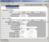
  4. Normally the Battery and Calibration Categories will not show the factory calibration parameters ('Show Protected Settings' is unchecked).

    CA3_SetupUtility_NoProtected.png

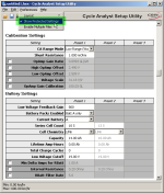
    Use the menu to 'Show Protected Settings' - new shaded parameters will appear with checkboxes.

    CA3_SetupUtility_ProtectedDisabled.png
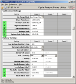
  5. Enable 'modification and write' of all shaded parameters by enabling the checkboxes.

    CA3_SetupUtility_ProtectedEnabled.png
  6. Make any desired setup modifications.
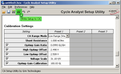
  7. Write the complete suite of parameters to the V3.

    CA3_SetupUtility_ProtectedWrite.png
Done!
 
What are the signs of corrupted EEPROM? Would lack of throttle response even after doing the green wire mod on a 'Large screen compatible' controller fall in this boat?
 
cal3thousand said:
What are the signs of corrupted EEPROM?
Typically an inability to set the RShunt value (or other values), or a loss or scrambling of settings.

cal3thousand said:
Would lack of throttle response even after doing the green wire mod on a 'Large screen compatible' controller fall in this boat?
Nope - something else at work there - probably settings...

Exactly what does "lack of throttle response" mean?
Inoperative, poor power, laggy performance?

What are the details of "the green wire mod"?
If from the earlier Guide version I'm guessing reconnecting the CA-DP cable ThrottleOut wire to controller ThrottleIn?
 
I have set the CA3 to three presets with a Grin three position switch for selection. Low is set to PAS disabled, medium to auto-pas 100 watts, high to auto-pas 250 watts. I want to be able to maximize exercise hence no assist and then be able to quickly switch to an assist level consistent with my level of cardiac distress. Yes, low works - has zero assist but medium and high presets are always the same ie, the last numbers entered. What am I missing? :?

The analyst is an awesome piece of technology and probably be kept out of the hands of a baboon. LOL Justin has been fantastic about responding to basic set-up questions but I don't want to waste his valuable time on this. The complete Ezee kit from Grin is well worth the cost in plug and play installation not to mention power at 48 volts. :D

A suggestion that I made to Justin was to add an a section on what the short forms used in the manual mean/represent. Experts on the forum will have no need but for somebody like me a simplified set-up manual in plain language stripped of the extra technical details would be appreciated. Wating for the half twist throttle to be delivered and then will see if I can do a better job setting it up. Not a complaint about the manual but it is far more than I need.

Townie is mobile no matter what whiat issues with pas and throttle. EV smile a kilometer wide. :mrgreen:
 
Hallo boys, i can use this thermistor with CA v3?
http://it.rs-online.com/web/p/termistori/0151237/

http://it.rs-online.com/web/p/termistori/0151237/

Thanks to all! :)
 
Fishy1 said:
A suggestion that I made to Justin was to add an a section on what the short forms used in the manual mean/represent. Experts on the forum will have no need but for somebody like me a simplified set-up manual in plain language stripped of the extra technical details would be appreciated. Wating for the half twist throttle to be delivered and then will see if I can do a better job setting it up. Not a complaint about the manual but it is far more than I need.
Ya - the manual isn't really light reading - it's difficult to find a level that satisfies all. Sadly, the very flexibility of the device and the many possibilities for installation make it necessary to discuss many options - and failing to do so leaves a new user with no idea that some small difference in his situation actually requires different handling. That said, even with the added How-To pictures in the latest version, a more watered down version for the most common installation (using all 'new' contemporary parts and 'normal' operation) is certainly possible.

Fishy1 said:
I have set the CA3 to three presets with a Grin three position switch for selection.
  • Low is set to PAS disabled,
  • medium to auto-pas 100 watts,
  • high to auto-pas 250 watts.
I want to be able to maximize exercise hence no assist and then be able to quickly switch to an assist level consistent with my level of cardiac distress. Yes, low works - has zero assist but medium and high presets are always the same ie, the last numbers entered.

What am I missing?
You missed the part about global and preset-specific parameters -- p8 of the Guide:
Unofficial User Guide said:
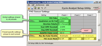
Note: Certain Setup parameters have global significance and are not part of any preset (e.g. tire circumference) while others are preset-specific (e.g. number of battery cells) and may be set differently in each preset. To determine if a parameter is global or preset-specific, see the most recent configuration summary file listed in this post. Individual Setup parameters are described in detail on the Grin Tech V3 web page.
This can also be seen by launching the CA3 Setup Utility -- parameters that only appear in the 'Preset 1' column are really 'Global' not 'Preset 1' and so cannot have unique values in different presets:

PasWattsParameterType.png
So - your presets 2 & 3 cannot work as you expected because PAS->PASWatts is a shared global parameter and the 'last' setting you made applies to all presets as you observed.

There are a few strategies to address this:

  1. Use the fact that PLim->MaxPower (preset-specific) overrides PAS->PASWatts (global) to set different PAS limits indirectly in presets 2 & 3 via MaxPower. This has the downside of also limiting the available throttle power (probably Not Good).
  2. Use the AutoTorqPAS technique described in the Guide (p 48) for Preset 3 so you will get RPM-based PAS in that preset with a different power limit distinct from PASWatts which will control Preset 2. This technique is sketched out in this post for a member who similarly desired different PAS levels in different presets.
  3. Reconfigure your 3-position switch to exclusively control PAS Assist (something like 0%, 40%, 100%). You can still have presets, but you will need to use the console buttons to switch them. Post back if you want to do this - the setup may be non-obvious using the off-the-shelf Grin switch.
  4. As a variation on the previous approach, replace the 3-position switch with one of the new plug-and-play pots from Grin to get infinitely adjustable PAS assist level (very nice... :D ).
  5. Use the adjustable 'Virtual Torque' technique to add variable RPM-based PAS assist in a addition to the existing 3-position switch - which could be used for any normal AuxPot functionality (p. 51 of the Guide). This requires some wiring though, and from your other remarks, may be out of your DIY comfort zone. This is what I use....
So many options!
As mentioned above, it's sort of tough to figure out what level of detail and how to organize a manual for all possible users and possible installations... :D
 
Hi all,

I want to connect my Thun torque sensor to my CAv3. However, I am running a 14S Pack from Paul (EM3EV) which gives me 58.8V HoC. What are the tolerances for powering the Thun directly from my CAv3, and should I indeed run the Thun from a separate DC-DC converter (58V-10V)?

Thanks!
 
hjns said:
I want to connect my Thun torque sensor to my CAv3. However, I am running a 14S Pack from Paul (EM3EV) which gives me 58.8V HoC. What are the tolerances for powering the Thun directly from my CAv3, and should I indeed run the Thun from a separate DC-DC converter (58V-10V)?
It sort of depends on what other things you have attached to the CA. There is a bit of headroom in the V3 so you should be able to run a Thun and throttle. As I recollect, the 1500mw limit in the tables and equation on p.44 of the Guide is at least 10% conservative.

Take an inventory of your current draw. You might also just measure the whole shebang at pin 1 of the CA-DP connector - this will eliminate the guesstimates for the 10ma CA draw, Thun spec sheet 20ma, etc. This is a matter of (slowish) regulator overheating and you are not hugely over the limit so hooking it up for a brief test is safe.

If you estimate or measure that the bike is drawing too much (even assuming the extra headroom), just run your throttle, 3-position switch, or other 5v accessories from the controller throttle +5 lead (probably presently unused), and leave the V3 to provide only the 20ma Thun +10v which it can do with no difficulty.

No point in adding a DC/DC converter if you can just offload the 5v stuff back to the controller... :D
 
Another alternative is to add a small dropping resistor to the V3 to get a few volts drop in Vbatt to the CA V+ pad to pick up a little regulator current capacity. You would also need to add a couple of additional resistors to monitor the voltage on the Vbatt side of the dropping resistor using the Vext pad as described in the Guide (Section 5.8 'High Voltage Vehicle Support'). This is a bit of fussing around but would eliminate the extra +5v wire running to the bars - if you are really concerned about that. Post back if you want to pursue this and the Guide isn't sufficiently clear...
 
teklektik said:
hjns said:
I want to connect my Thun torque sensor to my CAv3. However, I am running a 14S Pack from Paul (EM3EV) which gives me 58.8V HoC. What are the tolerances for powering the Thun directly from my CAv3, and should I indeed run the Thun from a separate DC-DC converter (58V-10V)?
It sort of depends on what other things you have attached to the CA. There is a bit of headroom in the V3 so you should be able to run a Thun and throttle. As I recollect, the 1500mw limit in the tables and equation on p.44 of the Guide is at least 10% conservative.

Take an inventory of your current draw. You might also just measure the whole shebang at pin 1 of the CA-DP connector - this will eliminate the guesstimates for the 10ma CA draw, Thun spec sheet 20ma, etc. This is a matter of (slowish) regulator overheating and you are not hugely over the limit so hooking it up for a brief test is safe.

If you estimate or measure that the bike is drawing too much (even assuming the extra headroom), just run your throttle, 3-position switch, or other 5v accessories from the controller throttle +5 lead (probably presently unused), and leave the V3 to provide only the 20ma Thun +10v which it can do with no difficulty.

No point in adding a DC/DC converter if you can just offload the 5v stuff back to the controller... :D

Hi Teklektik,

Thanks for the reply. I understood from your CAv3 Manual that this additive power calculation is valid for the V+ pad on the CA. Now I understand that this is also valid for the dedicated power output on the CA PCB for the Thun. This makes me feel much more comfortable.

I run my throttle and my thermistor from the CA, in addition to my planned Thun. I will meausure the current through pin 1 of the CA-DP connector without and with Thun. Great point on the 5V lead from the controller. No problems bringing that one towards the CA for the throttle.
 
Yah, tried to get a plug and play potentiometer from Grin when I ordered my Ezee kit but they're out of them. Not sure if they are going to carry them again.

Thank you for prompt reply. Back to limits on aux with zero percent as level one on switch does the trick. Justin indicated that three PAS settings for each preset might be in a future software release. The work involved in developing the Cycle Analyst must have been mind boggling.

GRIN RULES :mrgreen:
 
Back
Top