Mounting Turnigy Watt Meter

the little shunts have a specific solder plane they have to be soldered onto so that the specified value is produced across the shunt. you will find it on the data sheet. the trimpots are there to adjust the inputs to the op amps that provide the amplification of the voltage across the shunt.

also i just checked on the most recent of my $13 cheapo wattmeters like in the picture and they do not have the trimpots like they used to.
 
I have this GT power watt meter but the reading is not accurate, it's way off. It reads current at exactly 200ma less than the actual current. If i put a 1A load it reads 0.8 or what every load i put it reads exactly 200ma less. I have two multimeter which is accurate and it reads the current accurately. Is there a way to calibrate it? I opened the GT watt meter and there is no adjustment inside.
 
netwarri0r said:
I have this GT power watt meter but the reading is not accurate, it's way off. .
it's maybe just a mix up between "precision" and "exactness" - above all, mine also have a .2 constant mismatch when comparing to separate multimeters measurement, ...and I am fine with that, (it's 0.4% unexact on a 50+ reading :lol: )
 
This GT watt meter is useless for me because i am using it to test battery capacity. Maybe i should get the more expensive watt meter like watts up.
 
What about this cheapie? Looks like no modding required
http://www.ebay.com/itm/New-100V-100A-DC-Digital-Voltmeter-Ammeter-LED-Amp-Volt-Meter-Current-Shunt-/291079963241?hash=item43c5b7c269
Has anyone bought smth like this?
 
That volt amp meter requires a supply voltage between 4.5V and 30V.
Ok to run off your battery if using 24V nominal but if using a higher voltage battery pack then you'll need a step down voltage converter or a low voltage tap off your battery.
 
rmrf said:
What about this cheapie? Looks like no modding required
http://www.ebay.com/itm/New-100V-100A-DC-Digital-Voltmeter-Ammeter-LED-Amp-Volt-Meter-Current-Shunt-/291079963241?hash=item43c5b7c269
Has anyone bought smth like this?
It needs a low voltage power supply, which adds complications for use on an electric bicycle.
 
d8veh said:
rmrf said:
What about this cheapie? Looks like no modding required
http://www.ebay.com/itm/New-100V-100A-DC-Digital-Voltmeter-Ammeter-LED-Amp-Volt-Meter-Current-Shunt-/291079963241?hash=item43c5b7c269
Has anyone bought smth like this?
It needs a low voltage power supply, which adds complications for use on an electric bicycle.
Not necessary, it can work from the same battery if the voltage is lower than 30V (which is the case on many bicycles)
 
Well, he's from Sweden; maybe the EU limitations enforced there prevent many from going to more than "24v" systems (which tend to be 28-29V hot off the charger, at most)?

For prebuilt bikes I imagine it's common, too, particularly in the EU.

But I'd guess that from the kits I've seen people building from on ES, even low-power noob stuff, 36v is more common, and 48v getting to be.
 
As far as I can see, 24v bikes hardly exist in Europe. They were more common before 2010, but now there's only a handful, normally offered by the big chain stores. I doubt that you'll find one in a normal electric bike shop.
 
Anyone know what these shunts are called to just purchase a handful of these shunts rather than the entire unit? tried searching through digikey but theres pages and pages under shunts... just want an inline shunt to sneak into a loom for a little project I'm working on...
 
I have been using a cheap GT Power watt meter (Turnigy clone) on my handle bar for quite sometime (5-6 months) before I came across this thread. As usual, I ran big wires 4 x 6sq.mm = 2 x forth and 2 back to and from the batt pack and the GT Power and that bothers me everytime I look at it.

I unpacked a new GT Power meter (same model) and did the mod today per Jereme's post but did not succeed. The watt meter showed correct voltage but amps, watts & wh always read 0. Just like the R shunt is 0 ohm and the meter cannot detect V drop across R shunt.


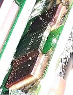
ShuntMod-Turnigy-20181229_2.jpg


ShuntMod-Turnigy-20181229_3.jpg


ShuntMod-Turnigy-20181229_5.jpg


View attachment 9


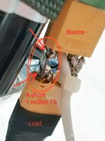
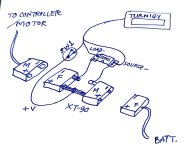
There are 3 wires, 24AWG from old USB cable and about 5-ft long ;

1 power from 14S5P batt pack + BMS (output taken from BMS) >> to the source -
1 in-between BMS & controller >> to load -
1 V+ (+14s) to where the red thick wire connected on the pcb of the GT Power


ShuntMod-Turnigy-20181229_11.jpg


View attachment 8


69203.jpg


69204.jpg


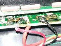
It looks like my solder is so poor with breaking copper wires from above picture, But in reality, it is much better than it looks. :wink:


69202.jpg


View attachment 4


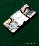
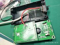
These connections are corresponding, point to point, to how the R shunt connected on the GT Power's pcb. Just move the R shunt to a different location. "source-" and "load-" are per GT Power's front panel.

I soldered this removed R shunt in between 2 XT-90 connectors, back to back on the negative terminals. While the positive terminals were directly connected. Then connected the wires and ran it into the watt meter box with a small switch to power it ON/Off.


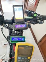
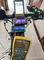
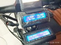
Below shown 2 meters measuring the same e-bike and from the same batt pack and at the same time.

+ The top meter is an old one I used for 5-6 months, connected to batt pack with thick wires.
+ The below meter is a new one I mod today. Vpack is OK but it does not read amps, watts & wh and the peak value as the top one.
+ Phone screen shows Vpack from bluetooth BMS, which is similar to the new watt meter's reading.

The 2 meters read a little differently but that is acceptable for now.


View attachment 2


View attachment 1


69212.jpg


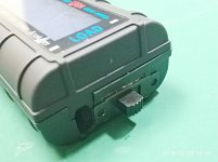
There is no trim pot to adjust anything in this GT Power model.

This mod is so simple that nothing could go wrong but it did.

Anyone experienced this and how to make it work ?
 
ichiban said:
I unpacked a new GT Power meter (same model) and did the mod today per Jereme's post but did not succeed. The watt meter showed correct voltage but amps, watts & wh always read 0. Just like the R shunt is 0 ohm and the meter cannot detect V drop across R shunt.

*is* there a drop across the shunt? You should be able to measure it, though it will be very small.

If one of the sense wires to the TWM from teh shunt is broken inside, you would measure a drop across the shunt, but not at the meter. (and a continuity test would also fail).

If somehow the shunt is shorted (a bit of solder, etc) it might not have any drop across it.

It's also possible the op-amp that's used to amplify that voltage drop for the MCU is defective or damaged. Or has a solder issue from the factory, etc.


Note taht if you ahve the wires backwards from the shunt, the TWM won't read anythign since it only reads "forward" current. If it will read regen curretn flow from the controller (load) to the battery (source) now, then that's what's wrong.

It could also simply be a defective meter--you said it was new but had it ever been tested before modding?
 
Thanks amberwolf. You are always my guardian angel ! :D :thumb:


Unfortunately, I've done some checking to confirm like what you suggested. There's some voltage across R Shunt sense pads up to the meter itself. Everything looks fine but the display still shows 0. I have not tested this GT meter before, just freshly opened the box and did the mod. So looks like my new meter is defective. I might hv to resolder the R shunt back to its box see what it will do.

I have to go outside for a while. I'll post some pictures tonight of what I hv done.

Thank you again.
 
new GT Power R shunt mod 2018.12.30


Here are what I have done to find out where should the problem be at :

Both old and new (mod unit) GT Power meters connected in series, measuring the same current flow to the same controller & motor.


1) Check V across R shunt @ remote location : out from BMS & batt pack

- V shunt measured across new R shunt shown 2-8mV (Fluke 117 on mV range)

when thumb throttle press hard on PAS 9. New GT Power display showed 0 amp/w/wh.
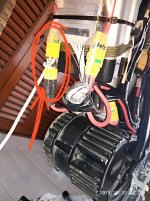


69409.jpg


69411.jpg


I measured V across R shunt where arrows point.

Result (from Fluke 117) corresponds to our assumption : current flow results in V across R shunt.

That means R shunt is not damaged and works properly. I did not take picture here but

confirm that new GT Power showed 0 amp/watt/wh. It is hard to take picture by myself

doing that measurement.


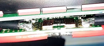
2) Check V across original pads (on new GT Power pcb) where R shunt was (before

removed)

- V shunt measured shown 2-8mV (Fluke 117 on mV range) on PAS 9. Result :
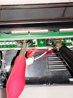


69314.jpg


69317.jpg


69321.jpg


Current is 2-8mV / 1 milliOhm = 2-8amps. Results looks OK. Accuracy might

be off quite a bit but it shows that the R shunt did sense current flow at the watt

meter pcb. So connecting wires should be OK but display show 0 amp/w/wh/peak.


From above measures, I think there is something wrong with the circuitry inside the

new GT Power. I might have to move the R shunt back to its original location to see

if the meter works properly. If not, that shows the meter is defective, either on arrival

or I damaged something during removal of that R shunt. If it works OK, I will have to

remove the R shunt back to the remote location again to see if it is OK this time. Lots

of works, is that worth it ?


Questions :

1) member dr_frost_dk posted Mar 08, 2014 re :

https://endless-sphere.com/forums/viewtopic.php?f=2&t=21976&start=125#p863722

...i was locked at 137.??A like others complained about, but this was due to

connection missing at output - connection, there is a very small pad that needs to be

connected to the BIG pad, after that it worked as it should ...

Which "very small pad" is that ?


2) Probably I might order some new R shunt 1mOhm 1% to replace the original one

to see if it will do any good. My original GT Power (with big wires) still works Ok but

it is UGGGGLY. LOL


3) May be I will replace another set of bigger/new connecting wires to see if it will

work. Old one was about 5-ft long, 24awg from old usb cable.


Any comments ?
 
Big coincadink! Just came across this thread and this last post was today, lol. Sorry, I have no advice, atm. I've just completed purchasing all items for upgrading my scooter. Last item I ordered was the G.T. Power watt meter. I hope you you or someone can find a way to sort your problem out. I'd like to do the remote shunt idea as well. More interested in volts, so shouldn't be a problem. Good luck, bro.
 
Found this while browsing watt meter shunt mods. It's d8veh's post he linked to earlier in this thread. The link was broken, but this one works. I'd like to try this myself, but I'm using 12s lipos and 10 awg wire. He says to use 14 awg for the shunt. I'm wondering if that size wire can handle the current. Might try using the original shunt instead. Probably get the same issue you ran into.

https://www.pedelecs.co.uk/forum/threads/the-best-value-wattmeter.16869/
 
Back
Top