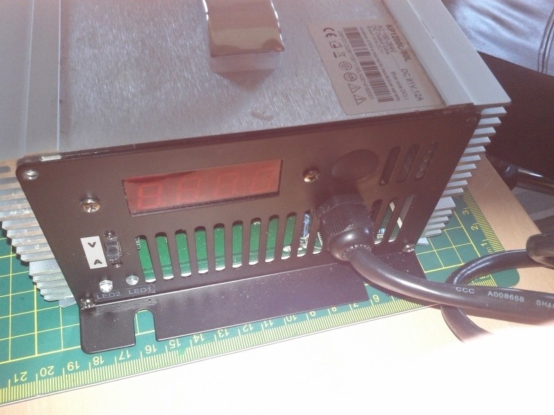
cal3thousand said:End of cycle while "on the road" will be handled by me, so a display or current would be nice
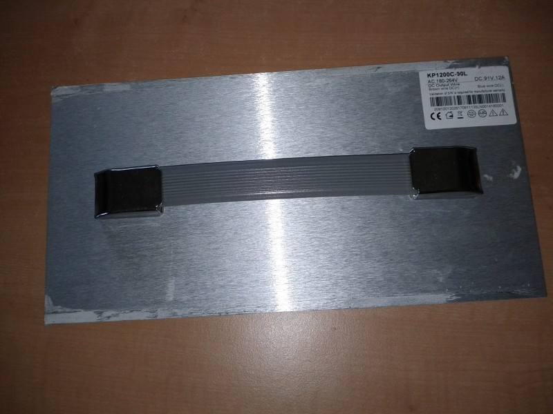
because of this i think the meanwell led supplies are optimal for travelling or even installation to the bike (some are waterproof)
you can simple add a display like this:
http://www.endless-sphere.com/forums/viewtopic.php?f=14&t=57195
you will find much more different ones on ebay if you search for "ammeter voltmeter"
")