Emergency "Bad Boy" ultra Compact charger

Somewhere I drew up a schematic for a voltage cutoff that uses a solid state relay to kill the input power whenever the output reaches a set voltage. Kind of a crude CC-CV supply.

I think the output filter cap might be a good idea or alternately a hefty inductor to reduce the ripple current getting to the cells. Adds weight/size I know, but there were reports of battery cells making a buzzing sound during charge (probably bad).
 
Pardon my ignorance, but couldn't you arrange the diodes differently and cut the peak-voltage in half by ignoring the negative cycle of the sine wave? You're throwing away 50% of the energy but shouldn't that work or am I just wrong here..?
 
Unfortunatly not. You would get the same voltage, but the ripple would be half the frequency. Have a look at half-wave vs full wave rectification on senior google.
 
fechter said:
Somewhere I drew up a schematic for a voltage cutoff that uses a solid state relay to kill the input power whenever the output reaches a set voltage. Kind of a crude CC-CV supply.

I think the output filter cap might be a good idea or alternately a hefty inductor to reduce the ripple current getting to the cells. Adds weight/size I know, but there were reports of battery cells making a buzzing sound during charge (probably bad).
Fechter, you certainly did, it was in my topic. Those interested can read it there.
 
Frank said:
I don't think the capacitors on the output side of the bridge do anything - the batteries act as a large capacitor.

Hi Frank,

The capacitors are needed to smooth the voltage ripple. It'll be about 3 volts with properly sized caps, and 165 volts without. How fast do you want to melt your primary wires?

Near end of charge, you'll want as little ripple as possible.
 
Thanks for the links...

I think I have found the one I was looking for..well someone else found it for me, but I can't find either right at this moment. but schematic printed out, and searching for parts as I can find the time
 
No but I am still tempted to try it. I now have my old nano tech 20s 4 p pack...now 3p...may try it on that...just the basic version..two components.
Capacitor in series with the input of the bridge rectifier apparently 24micro farads gives about 1 amp charge current.

The battery goes directly across the output of the bridge rectifier.
this is the sort of thing you would use for 5 or 1o minutes..while standing watching the bike.

I'd do it with the bike powered on and viewing the CA display for the voltage...or put a cheap in line ammeter/voltmeter or standalone CA so to monitor the charge.
 
file.php


Well I knocked one of these up yesterday as I found an unknown amperage ( 30 I guess) one inch square bridge rectifier, and had a 300uF 300VAC cap kicking around.

I had read on one of these threads that approx 25 uF equals about 1 amp of charge current...but I am now guessing that that figure relates only to a certain voltage pack.

Here is what I found.


at 240 volt AC input
with a 20s 3 p pack so 84 volts...cant remember the IR..but it was lower than the second pack I tried.

This first pack started at 74 volts and rose in a few minutes up to 82 volts with a constant charge current of 8 amps.

I then tried a single 4 series 5 ah pack, so 16 volts, with a much higher internal resistance than the big 20s3p pack.

that gave a charge current of 24 amps.

interesting..
 
NeilP said:
Well I knocked one of these up yesterday as I found an unknown amperage ( 30 I guess) one inch square bridge rectifier, and had a 300uF 300VAC cap kicking around.
Hi Neil,

Nice work! Wikipedia also describes the characteristics of this circuit.

bridge.rectifier.png

But you need to be careful with the residual high voltage in the Capacitor. Touching that Cap after charging could be nasty! :shock: Have you considered adding a small resister to bleed off the capacitor after the 240V mains power is removed? Wikipee warns us that:

The simplified circuit shown has a well-deserved reputation for being dangerous, because, in some applications, the capacitor can retain a lethal charge after the AC power source is removed. If supplying a dangerous voltage, a practical circuit should include a reliable way to discharge the capacitor safely. If the normal load cannot be guaranteed to perform this function, perhaps because it can be disconnected, the circuit should include a bleeder resistor connected as close as practical across the capacitor. This resistor should consume a current large enough to discharge the capacitor in a reasonable time, but small enough to minimize unnecessary power waste.

Good luck, and be safe! Done carefully, this could be a very handy device to have on tour. BTW, how hot did the components get? 8)

Cheers,
Holocene
 
.707 x 1/2 Vp-p (peak to peak). For 240v sinusoidal, that would be about .707 x 120 = 84.84 volts DC RMS.
If the capacitor is beefy enough, it will smooth out the very ripply DC, but it will get hot for high current draws.

Now this thing won't have much "taper" to the charge: it's gonna sink as much current through the battery as it can, because you've got that very low resistance battery in parallel with the filter capacitor.

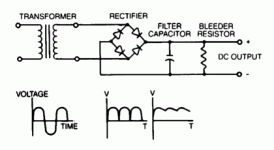
Here's a google-found photo showing what's happening with the waveform:
pwr-supply-fullwave-net-420.gif
And here's the background info on the process. It's actually part of the study guide for a ham exam:
http://www.n9xh.org/license/pcara_general_upgrade_lesson_07.pdf

And BTW: the transformer is there to provide both voltage transformation (usually step-down) and isolation from power line faults and spikes.
Voila: you have the basic linear power supply from times of yore....
 
You guys are using the function of the cap wrong in those schematics.

The cap is to limit the AC current draw and belongs in the AC side (and must a non-polar cap made for AC current).

The battery doesn't needs it's DC ripple filtered by a wimpy little cap, the battery itself is a massive capacitor that smooths whatever choppy pulsed DC you feed it.
 
Yep, LFP is right. I had been meaning to post back but not found time.

The big cap on AC side is to provide the limited current limiting.

The whole idea of these 'bad boy' chargers is cheap nasty and dirty quick and small and simple.

As soon as you start adding transformers etc you are adding a layer of complexity and weight.

Either earlier in this thread, or another similar thread, it was stated that 25 uF gives about 1 amp of charge current.
My tests at 240 VAC, with a 4 series high IR single pack, and a 20s3p LOW IR pack showed this was not true.

The high IR 16 volt pack in conjunction with the circuit I posted, allowed 24 amp charge current to flow, where as the pack with low IR but higher voltage (20s so 80 ish volts) allowed only 8 amp to flow.


In answer to earlier question, about components getting hot.... I don't know, I did not let it run for more than a minute or less. Certainly the cap and rectifier were not hot,
I had battery medic on the packs, and I only had packs charged to about 3.8v per cell, and were a little unbalanced. I started to see some cells hit 4.19 so I powered off.

Need to try again with a much more fully discharged and better balanced pack.

This charge idea is not to fully charge a pack, just to grab a few sneaky Ah when out and about and running a low Ah pack.

My current build will only have 8ah capacity, so want a compact robust way to take pack up when I get down to 5 or so Ah used.
 
The circuit with inline cap on AC side is 'self regulating ' with regard output DC voltage.

The voltage on the output only rises enough to allow current ( as restricted by the AC side cap) to flow to the level the cap will allow.
This is how you can connect any voltage pack across the DC side.

You do have to continuously monitor though, as output volts will keep rising to continue pushing amps through the pack. So walking away is NOT an option. Plug in battery first, then AC , and sit and watch pack voltage.
 
Is it just me, or could you both improve the power factor and increase charger output for a given electrical circuit breaker limit by adding an inductor in series with its output to the battery?

It would likely weigh as least a pound though, because working in these low frequencies is pretty caveman.
 
Umm yea, I don't see why not..need to think..but it is a bit of extra space as opposed to weight really.

I only want something like this for a quick 20 amp 5 minute max boost to charge, plugged in where ever.

All UK domestic power sockets are all 13 amp and 240 volt. and plan to make this up with a very short power lead..12 - 18 inch sort of size, and small box holding the cap and rectifier.


I am just wondering about the AC capacitor and its current limiting. From what I had read, the capacitor gives the current limiting..but it seems very variable as to the current it allow...far far greater variation than i was expecting..and in the wrong sense . The High IR pack gave the highest current...but it was the lowest voltage.

I have virtually zero theoretical knowledge, and just have the basic grasp of why the cap causes current limiting.


OH, BTW Luk, your Youtube vid..the worlds most dangers e-bike..that is my stock link when people ask me about how powerful can an e-bike be...that Start comment.." You know the bike is dangerous" ...followed by the bloke flipping it..just classic :p
 
NeilP said:
I have virtually zero theoretical knowledge, and just have the basic grasp of why the cap causes current limiting.

Think about it as the average energy transfer rate when the low frequency 50/60hz charges and discharges that capacitor to whatever voltage offset. As the voltage off-set climbs, the amount of energy transferred from the caps increases at the square of the voltage difference. If you increase the cap value, you increase the coulomb of charge on each cycle, as it took higher average current to charge and discharge that larger capacitor on each cycle.


NeilP said:
OH, BTW Luk, your Youtube vid..the worlds most dangers e-bike..that is my stock link when people ask me about how powerful can an e-bike be...that Start comment.." You know the bike is dangerous" ...followed by the bloke flipping it..just classic :p

Thank you my friend, I am so glad that video can share awareness of the potency of EV's with the world.

ATB,
-Luke
 
liveforphysics said:
Think about it as the average energy transfer rate when the low frequency 50/60hz charges and discharges that capacitor to whatever voltage offset. As the voltage off-set climbs, the amount of energy transferred from the caps increases at the square of the voltage difference. If you increase the cap value, you increase the coulomb of charge on each cycle, as it took higher average current to charge and discharge that larger capacitor on each cycle.

OK< yes, that is pretty much waht I was thinking, but in more simple less tech terms..the bigger capacitor, more cgharge required to charge it, therefore greater current flow.


With the same capacitor, I have had a current of 8 DC amps when across a low IR, 80 volt (20s4p ) lipo pack and high current (24 amps ) on a much higer IR 4s1p pack.

I was expecting the current to be higher on the low IR pack, and lower on the high IR pack...but it seems from experience and what you are saying , if I understand correctly, that the pack voltage plays a greater part itn he likely current flow than the pack IR.

I will paly aroudn some more this weekend

Thanks for the info.
 
NeilP said:
liveforphysics said:
Think about it as the average energy transfer rate when the low frequency 50/60hz charges and discharges that capacitor to whatever voltage offset. As the voltage off-set climbs, the amount of energy transferred from the caps increases at the square of the voltage difference. If you increase the cap value, you increase the coulomb of charge on each cycle, as it took higher average current to charge and discharge that larger capacitor on each cycle.

OK< yes, that is pretty much waht I was thinking, but in more simple less tech terms..the bigger capacitor, more cgharge required to charge it, therefore greater current flow.


With the same capacitor, I have had a current of 8 DC amps when across a low IR, 80 volt (20s4p ) lipo pack and high current (24 amps ) on a much higer IR 4s1p pack.

I was expecting the current to be higher on the low IR pack, and lower on the high IR pack...but it seems from experience and what you are saying , if I understand correctly, that the pack voltage plays a greater part itn he likely current flow than the pack IR.

I will paly aroudn some more this weekend

Thanks for the info.
It is actually pretty linear with the V difference. I made one and if I remember well, there is starting cap 280-320mF (It is enclosed in alloy shell now need disassemble to confirm). On 24s pack I get ~7Ah from 110V and ~14Ah from 220V and ~14Ah on 12s at 110V, all lipos and 60Hz grid. As LFP says, cap is only seeing V difference between battery and grid V, more difference more capacity of the on capacitor is used, frequency will play big role as well.
P.S. starting cap are smaller but not the best choice, better to use running caps. My assembly (in alloy charger enclosure) gets uncomfortably hot in ~ 30min, no fan used, capacitor contributes to heating a lot. If I remember well, quality Run capacitor do not heat noticeably. LFP linked cool device yo can integrate to stop charge:
http://www.ebay.com/itm/181209317394?_trksid=p2055119.m1438.l2648&ssPageName=STRK%3AMEBIDX%3AIT

Have fun!
 
I assume the output on this thing floats at ~330V? Likewise if the cap fails short-circuit the output goes full voltage and current?

I'm pretty sure I've seen these circuits crop up on the 'net before and always accompanied by dire safety warnings. Even to my inexpert eye I can see the output is completely unisolated from the input...
 
liveforphysics said:
Is it just me, or could you both improve the power factor and increase charger output for a given electrical circuit breaker limit by adding an inductor in series with its output to the battery?

It would likely weigh as least a pound though, because working in these low frequencies is pretty caveman.

I think it would help. People have reported the batteries actually making a buzzing sound during charge, which is probably not a good thing. Using a big inductor will smooth out the current peaks, but will also add weight and heat as you point out. The old vacuum tube boat anchors I used to play with almost always had a power supply choke that was about half the size of the transformer. It would be fairly easy to make your own by cutting off the windings from a transformer core and wind it with the smallest wire that will handle the expected current (a little bigger wire will help heating).
 
Punx0r said:
I assume the output on this thing floats at ~330V? Likewise if the cap fails short-circuit the output goes full voltage and current?

I'm pretty sure I've seen these circuits crop up on the 'net before and always accompanied by dire safety warnings. Even to my inexpert eye I can see the output is completely unisolated from the input...


You are right on all accounts. It is not without good reason that this thread title implies an inherently unsafe unregulated charger for emergency use.

This is NOT the charger for noobs. This is not a safe charger design. This charger design should be done by nobody who doesn't very thoroughly understand it's operation and unique risks, like if you forget and leave it plugged-in, you're choosing to have your vehicle engulfed in a large ball of intense fire and plasma and hazardous smoke.

This device's function is to weigh as little as possible while still being able to quickly top-up your pack with a few extra Ah. This device is NOT EVER intended for un-monitored use, and this device will certainly burn your vehicle down if you let it.
It can serve an occasional emergency charger function for those who understand it completely and don't let it burn there vehicles down.
Nobody is saying this charger concept is a good idea, because it's not.
 
Back
Top