Cycle Analyst V3 preview and first beta release

cal3thousand said:
  • #2: I've seen that someone else claim (but they didn't show how) to wire up a hack to access the controllers shunt for charging, eliminating the need for an external shunt.

Any help on this is appreciated

I use my controller's shunt for measuring charge going into the battery.

I do this by running out a pair of wires (+ and -) from the controller's power bus on the controller side of its shunt, then splitting it several times (so that I can hook up chargers in parallel or run other accessories off the ebike battery such as headlight, taillight, USB power port, etc.) and have their draw show up on the CA display. When it comes time to charge the battery I don't need to disconnect anything. Only need to connect my charger to one of these connectors so that current flows backward through the controller's shunt and into the battery.

This photo of the backside of an Infineon/LyenMKII EB312 board shows where I connected the leads.

A couple of points:


  • 1. Any power introduced to the controller after its shunt will not show up on the CA display nor be limited by the controller's internal current limit, although this is not much of a concern unless you're load-testing your motor system with a high-current charger or power supply connected.

    2. I usually leave the charger connected to the controller overnight and because I want the CA to record the re-charge stats, the controller must remain on for the duration. After the battery is charged, there should be no difference in voltage on either side of the controller's shunt. But, because I zero the CA* to ignore the controller's quiescent current draw and the quiescent draw of a couple of power converters connected after the shunt, the CA continues to see an apparent negative current flowing through the shunt for many hours after the battery is charged. This could amount to 1 to 2 Ah overnight. The longer I leave a charger connected in this manner to 'float' a battery following a charging session, the less accurate the Regen Ah display will be. So, unless I disconnect the charger soon after the battery is charged, the CA will show slightly higher Regen Ah than actually occurred.

I find this recharge-measuring capability most useful when I'm doing a quick recharge before a trip or during a trip, when the recharge may only be partial.

*One could connect a charger in this manner without a battery connected and then zero the CA so that when operating normally (without the charger connected) the CA shows all current drawn from the battery, including quiescent current from controller and any accessory converters.
 
mrbill said:
cal3thousand said:
  • #2: I've seen that someone else claim (but they didn't show how) to wire up a hack to access the controllers shunt for charging, eliminating the need for an external shunt.

Any help on this is appreciated

I use my controller's shunt for measuring charge going into the battery.

I do this by running out a pair of wires (+ and -) from the controller's power bus on the controller side of its shunt, then splitting it several times (so that I can hook up chargers in parallel or run other accessories off the ebike battery such as headlight, taillight, USB power port, etc.) and have their draw show up on the CA display. When it comes time to charge the battery I don't need to disconnect anything. Only need to connect my charger to one of these connectors so that current flows backward through the controller's shunt and into the battery.

This photo of the backside of an Infineon/LyenMKII EB312 board shows where I connected the leads.

A couple of points:


  • 1. Any power introduced to the controller after its shunt will not show up on the CA display nor be limited by the controller's internal current limit, although this is not much of a concern unless you're load-testing your motor system with a high-current charger or power supply connected.

    2. I usually leave the charger connected to the controller overnight and because I want the CA to record the re-charge stats, the controller must remain on for the duration. After the battery is charged, there should be no difference in voltage on either side of the controller's shunt. But, because I zero the CA* to ignore the controller's quiescent current draw and the quiescent draw of a couple of power converters connected after the shunt, the CA continues to see an apparent negative current flowing through the shunt for many hours after the battery is charged. This could amount to 1 to 2 Ah overnight. The longer I leave a charger connected in this manner to 'float' a battery following a charging session, the less accurate the Regen Ah display will be. So, unless I disconnect the charger soon after the battery is charged, the CA will show slightly higher Regen Ah than actually occurred.

I find this recharge-measuring capability most useful when I'm doing a quick recharge before a trip or during a trip, when the recharge may only be partial.

*One could connect a charger in this manner without a battery connected and then zero the CA so that when operating normally (without the charger connected) the CA shows all current drawn from the battery, including quiescent current from controller and any accessory converters.

mrbill,

This is helpful and I much appreciate it.

So this is what I'm reading: I only need to run leads off the negative and positive traces (aka Power Bus; <-- learned something today) and can also parallel off of them for multiple inputs.

To me, this seems like a modification that should be done to all CA-kitted controllers to allow charge monitoring. At least, I know what I'm doing with all my controllers. I will primarily be using the CA to monitor charge with bulk chargers/PSUs on the road so I can cut charge when I'm satisfied.

I wonder how this effects the lifetime/cumulative stats of the CA?
 
cal3thousand said:
This is helpful and I much appreciate it.

So this is what I'm reading: I only need to run leads off the negative and positive traces (aka Power Bus; <-- learned something today) and can also parallel off of them for multiple inputs.

Yes. It's not necessary to wire up parallel leads to charge through the controller's shunt. That was just an idea that extends the utility of connecting accessories to this point after the shunt.

What I call the "power bus" is just the Vcc or V+ and ground after the shunt inside the controller. If your controller is different, simply find the shunt, then discover which side is "inward-facing" and use that side to connect your negative charging/accessory lead. Find a spot where you can make a good high-current solder connection. Do likewise on the positive side, although you can split off the positive power supply lead for this if you wish to minimize the number of wires exiting your controller. Swap "positive" and "negative" in the above if your shunt is on the positive supply side.

To me, this seems like a modification that should be done to all CA-kitted controllers to allow charge monitoring. At least, I know what I'm doing with all my controllers. I will primarily be using the CA to monitor charge with bulk chargers/PSUs on the road so I can cut charge when I'm satisfied.

If one connected a high-current power supply or battery to this connector, one is essentially bypassing the controller's shunt and effectively disabling the controller's current limit. By offering a power connector here, a user could be confused and connect their battery to that connector instead of the intended power connecter that runs current through the controller's shunt. I can see sellers of controllers leery of offering high-current access to this point inside the controller. Perhaps by using a different charge connector (e.g. XLR) most user errors could be avoided, but the risk remains.

I wonder how this effects the lifetime/cumulative stats of the CA?

None that I've discovered. Cumulative stats are accumulated correctly, unaffected by Regen Ah. The CA records a trip after a certain number of Ah are drawn forward, no matter how many are pushed in reverse.
 
mrbill said:
If one connected a high-current power supply or battery to this connector, one is essentially bypassing the controller's shunt and effectively disabling the controller's current limit. By offering a power connector here, a user could be confused and connect their battery to that connector instead of the intended power connecter that runs current through the controller's shunt. I can see sellers of controllers leery of offering high-current access to this point inside the controller. Perhaps by using a different charge connector (e.g. XLR) most user errors could be avoided, but the risk remains.

Good point. I will 'key' my controllers' Andersons for charging as TOP/BOTTOM versus LEFT/RIGHT for Battery and will do the same for my road charger's DC output. This will keep me from accidentally plugging it incorrectly.
 
cal3thousand said:
So this is what I'm reading: I only need to run leads off the negative and positive traces (aka Power Bus; <-- learned something today) and can also parallel off of them for multiple inputs.
As mrbill noted, it's only necessary to pick up the (-) controller bus which is downstream of the shunt so the shunt can detect the charger current. The (+) can be picked up anywhere - either the internal controller (+) bus or externally (e.g. the red external controller Vbatt+ wire).

You may also wish to relocate the CA (+) lead running from the CA-DP connector so that the controller need not be powered to operate the CA. For instance, on my bike the key switch and kill switch are in series on the controller 'ignition' wires (one ignition wire is Vbatt+ the other is switched to run the controller 5v regulator). The CA power is taken off in between the two switches so the key switch turns off both CA+controller but the kill switch turns off only the controller leaving the CA running. This would largely eliminate the controller idle current snafu.

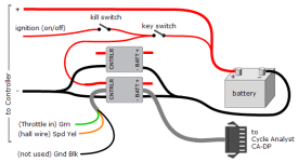
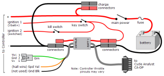
If you don't wish to mod your controller you can always use your external CA shunt both for charging and when underway and simply abandon the controller shunt entirely. In this case the charger wiring is all external and controller swaps use a stock unmodified part. The illustrations below are minor mods to the wiring in section 4.2.1.4 of the Guide -- the second also separates controller an CA power as described above. If you are using the controller hall signal for speed, add a connector to route the yellow breakout cable Spd wire to any {R,G,B} external controller hall wire. Since your controller is already CA-ready, you could also route the breakout cable Grn and Yel wires to a JST-6 connector and just plug them into the controller. Again, these are packaging considerations - the solutions are all equivalent from the CA perspective - other factors will determine the 'best' approach for a particular build.


ExtShuntWiringWithKeySwitch-Charger1.png
 
Originally posted in the feature request thread:

A feature I am used to from RC that I think will be very useful is being able to have an exponential throttle in -> throttle out curve.
I started to run test rides on the bike with the CA V3 and current based throttle and with my setup the first few mm of throttle travel make the bike jump forward and on the other hand, from half throttle to WOT there is not a big difference.
With an RC car and a programmable transmitter, I could just change the curve to be exponential and and gain more resolution in the start of the throttle movement and less in the end.
Of course, the curve can also be changed to have less resolution in the start of the throttle movement and more in the end to fix the opposite problem.

Avner.
 
teklektik said:
ferret said:
A feature ... that I think will be very useful is being able to have an exponential throttle in -> throttle out curve.

First - this is pretty much a dead thread.
Justin monitors the V3 Beta thread but not the whole forum, so posting off-thread risks things going by unseen by the one guy who really counts... :D

That said, requests for 'exponential throttle' come by once in a while although some sort of tunable non-linear response always seems what is actually desired not a true exponential curve. Something along the lines of what you request is possible with a few resistors as described in this post.

  • For instance, in the 'case 3' example, 50% throttle rotation yields 25% of the max output, effectively expanding the resolution of the leading part of the throttle.
You don't really indicate if you problem is an initial surge or not - not to be confused with you motor making extreme power for very little amps at the beginning of the throttle rotation. There are adjustments to minimize initial surge. Also, Current Throttle (either V2 or V3) cannot be more linear than the throttle driving it. If you have a wonky hall throttle that comes on hard, then the CA current limiting will do the same - it will still be current throttle but non-linear-in = non-linear-out. For this to work optimally, you need a nice linear throttle - a more expensive hall (eg Wuxing with single linear strip magnet instead of a magnet at each end) or a resistive throttle like a Magura.

A fully tunable non linear curve is of-course more flexible that just defining the exponential level, but I think just setting the exponential level is much easier to tune and can still give good results in most cases. I agree that if the fully tunable non linear curve feature was implemented, the exponential curve wouldn't be needed, but right now neither is implemented and I think that implementing, designing a user interface and documenting the simpler exponential curve feature would be easier and faster.

I read about the curve shaper but unfortunately it works only for resistive throttles, not the more common hall effect ones. Also, I think it if much better to be able to make these adjustment via software instead of hardware. The functionality of this method is useful and desired, it's just that experimenting with resistors time consuming ,can't be done on the fly and hard to roll back to a previous configuration compared with adjust a parameter on the CA.

I think that my problem is that motor is making a lot of torque for very little amps at the beginning of the throttle rotation. I'm sure what you mean by an initial surge, a PI control overshoot?
The controller gives about 30 Amps max. When staring from a standstill 5 amps are too much for a smooth start. That means that my initial throttle range is less than 17% of the full range and hard to modulate.
I don't think the linearity of my throttle is the issue or that current throttle is more linear. I think my throttle is close to linear, but I don't want it to be.

I guess I will be able to find a way around this problem, but I still think an exponential curve would have been a quick easy and intuitive solution.

Avner.
 
Too bad the throttle curve feature isn't available in the airplane R/C controllers like the CC Phoenix line. This would help those with R/C setups...
 
ferret said:
I read about the curve shaper but unfortunately it works only for resistive throttles, not the more common hall effect ones. Also, I think it if much better to be able to make these adjustment via software instead of hardware. The functionality of this method is useful and desired, it's just that experimenting with resistors time consuming ,can't be done on the fly and hard to roll back to a previous configuration compared with adjust a parameter on the CA.
Certainly a software solution would be preferred to the hardware approach in the post - it is offered only as a means to perhaps spend a Saturuday with some trimpots and a spreadsheet to alleviate a pressing performance problem and to give the opportunity to actually experience the non-linear curve solution. It certainly is in the 'hack' not 'product feature' category. If the matter is not that dire than this approach isn't worth the effort.

ferret said:
I started to run test rides on the bike with the CA V3 and current based throttle and with my setup the first few mm of throttle travel make the bike jump forward and on the other hand, from half throttle to WOT there is not a big difference.
ferret said:
I think that my problem is that motor is making a lot of torque for very little amps at the beginning of the throttle rotation. I'm sure what you mean by an initial surge, a PI control overshoot?
The controller gives about 30 Amps max. When staring from a standstill 5 amps are too much for a smooth start. That means that my initial throttle range is less than 17% of the full range and hard to modulate.
I don't think the linearity of my throttle is the issue or that current throttle is more linear. I think my throttle is close to linear, but I don't want it to be.
I made the remark about a lot of torque for very little amps thinking perhaps you had an astonishingly powerful motor so MaxCurrent was very large. However, your 30A current level seems modest (for a hub motor). I do note that you have a mid-drive build thread and if this is about issues with getaways in low gear with a 30A MaxCurrent, then you are no doubt running into a drive type issue since 30A is huge for low-gear low-torque requirements.

In any case, I am a little confused about what you are reporting.
  • If you are saying there is an initial jump to 5A or 17% throttle, then your throttle is clearly not linear.
  • If you are saying that you want to expand the low 17% rotation so that a substantial portion of the current range is 5A or less, then I would recommend an AuxPot switch to give you a slow mode.

    You seem to have a situation where a 50% increase in current (ie midrange to WOT rotation) yields little usable power increase - the power is definitely being delivered and expended so it must be going to heat I guess. (If this is a mid-drive in low gear, the motor is likely spun out and the added current is largely ineffective at pushing it further). Even a simple two position thumb switch for (50%) and (100%) modes would double the refinement of your control and help keep you out of this inefficient operating range except when needed.

    Let me be clear: I am not suggesting that this gives you anything like what you have requested - as with the resistor curve shaper suggestion, I'm just offering an existing solution that might help make your bike more drivable today. This is distinct from consideration of your feature request which is a 'futures' situation.... :D
 
An on the fly auxilliary pot display might be a nice addition to the CA3 monitor screens so that one would know at-a-glance what the pot was set at... In my case I'd like to use it to know what level assist is set at. 0-100% would suffice, but it'd be awesome if it would display the actual assist multiplier.

It would also be nice if 55rpm bottom cadence limit were made adjustable, so that applications (like mine) with low pedal cadence could be made to work without entering a false pas sensor pole count. As discussed in this thread I use a THUN, and have seen great performance improvement by entering a pole count of 4 as opposed to the actual 8, but this has implications for the calculated human watts and by extension the assist level because it's based on calculated human watts. It all works out in the wash and I just have to set the assist level down, and divide my HW/HWHrs by 2, but an ability to set the bottom cadence limit to a lower level seems like it would be a cleaner solution.
 
Hey,
back on Track with a new toy....

i need a little help...

i use a sabvoton controller now. it has a torque throttle (a real one)
for the throttle itself theres no need for a CAv3. So smooth and you can control it like a motorcycle.
But i want and need the limit functions from the CA. So i have plugged my Magura 5K Throttle in it.
Set in and Out to 0,0 - 4,75v (fault 4,99v)
works without a 1K resistor. why? donno....the CA shows me on Full Throttle only ~4,75v.
But in the Software of the Controller i see a clear 5,0v on Full Throttle.
(So the Fault Settings of the CA for Throttle comes not in play)
Can something bad happen here? i dont want a 10KW Full Throttle ride crossing streets.(in the wrong moment)

Iam not sure if i wired it up 100% correct (seems to be, because it works)
I have wired the Green Wire from Shunt to SPEEDSIGNAL of the Controllers Throttle connector. (Not the red(+) wire as i read in Manual)

like:

Controller +(red) .........to nothing
Controller -(Black).........to Shunt (Black)
Controller Signal(grey)...to Shunt (Green)
Controller Hall Yellow ....to Shunt (Yellow)

So whats iam asking for.

The Throttle is set to PASS-THRU
And i want no "limits or settings" from the CA to the Controller. Just the Pure Signal from Throttle to Controller.

What settings did i have to set to? (Throttle in/out?)

Ramp Time UP and DOWN to 99,9v/sec ?
Fast Rate to 0 Amps?
Power Limit Settings.....as i limit only to Power(Watt) i think only the WGain Setting is important
Set this to the lowest possible? I noticed on a Hall Throttle lower Wgain means quicker response.
My old setting was 20. Because it reflects this setting also to PAS. But maybe iam wrong.
Hope TEK is Online in a few hours :wink: :lol: :mrgreen:
 
Merlin said:
i use a sabvoton controller now. it has a torque throttle (a real one)
for the throttle itself theres no need for a CAv3. So smooth and you can control it like a motorcycle.
But i want and need the limit functions from the CA. So i have plugged my Magura 5K Throttle in it.
Hey Merlin! Sounds like an interesting new toy. It's interesting this comes up now because the matter of improved Current Throttle using phase amps instead of battery amps is a topic of conversation in another thread by a trials rider where snappy throttle performance is critical.

Because there was some experimentation going on there, I recommended that he revert the V3 to simpler V2 mode so the throttle would go directly to the controller (or via a Phase Current Throttle box), but I believe you are using the V3 for PAS so your PassThru strategy seems like the proper approach. (It should work fine for him as well, but with experimentation going on, complete segregation minimizes questions and finger-pointing...)

I have kind of busy US Holiday festivities going on today, so this is kind of quick, but here's some thoughts:

Merlin said:
Set in and Out to 0,0 - 4,75v (fault 4,99v)
works without a 1K resistor. why? donno....the CA shows me on Full Throttle only ~4,75v.
But in the Software of the Controller i see a clear 5,0v on Full Throttle.
(So the Fault Settings of the CA for Throttle comes not in play)
Can something bad happen here? i dont want a 10KW Full Throttle ride crossing streets.(in the wrong moment)
Here you want to continue using the V3 to match you throttle and controller voltage requirements.
  • You should restore the Magura and resistor and do the ThrI setup as you did originally (MinInput, MaxInput, FaultVolt). This will get you full throttle range and fault detection. If you didn't have the Magura and resistor originally and don't care about fault detection, omit the resistor and set Fault to 4.99v then adjust the input as per the Guide(will probably result in 0.00 and 4.99)
  • Next, set ThrO to match your controller specs: MinOut=0.00v, MaxOut=4.99v. This will expand your usable Magura input voltage to cover the entire 5v range of the controller - ensuring you can use all of the 10kW :D
Merlin said:
I have wired the Green Wire from Shunt to SPEEDSIGNAL of the Controllers Throttle connector. (Not the red(+) wire as i read in Manual)

like:
  • Controller +(red) .........to nothing
    Controller -(Black).........to Shunt (Black)
    Controller Signal(grey)...to Shunt (Green)
    Controller Hall Yellow ....to Shunt (Yellow)
Sounds like you are using a V3 external shunt, but I'm unfamiliar with your controller. If you can post a link to the manual I can take a look, but if I understand you correctly this sounds right.

Merlin said:
So whats iam asking for.

The Throttle is set to PASS-THRU
And i want no "limits or settings" from the CA to the Controller. Just the Pure Signal from Throttle to Controller.

What settings did i have to set to? (Throttle in/out?)

Ramp Time UP and DOWN to 99,9v/sec ? YES
Fast Rate to 0 Amps? YES
Power Limit Settings.....as i limit only to Power(Watt) i think only the WGain Setting is important
Set this to the lowest possible? I noticed on a Hall Throttle lower Wgain means quicker response.
My old setting was 20. Because it reflects this setting also to PAS. But maybe iam wrong.
Yep your Ramp settings look exactly right - this should 'open the pipe' and give PassThru Throttle a direct connect to the controller without any processing effects.

WGain will not affect your throttle response at all until you hit the max power limit set by MaxPower. However, as you point out, it will control the response of your PAS according to the Watt limits set up there. So - WGain should be left as it was at 20 to make the PAS work (to start with) and may require the usual tuning to get PAS working for you. Don't change the setting because of the throttle - it's normally not in play there.

Very interested in how this works out! :D
 
My cav3 has worked great with my "newer infineon 40 amp controller. Until it fully stopped all power due to reaching my 120 degree cut off. (It's the first time it's ever totally cut me off as usually I stop or notice the amps slowing me down enough)
Since then when I start the bike, the cav3 display starts as usual, but it takes about 15 seconds for the throttle to start giving power and when it does its under power (very low amount of power) for about 5 seconds until the bike comes back to normal.

I had been messing around with various power and speed limiting settings before that and have tried to put everything back to how it was before this problem.

Any ideas what's happening?

thanks.

Picture of my bike when I reached 120 cut off
10513373_10152558499089845_3642031206805481821_n.jpg
 
John Bozi said:
...when I start the bike, the cav3 display starts as usual, but it takes about 15 seconds for the throttle to start giving power and when it does its under power (very low amount of power) for about 5 seconds until the bike comes back to normal.
...
I had been messing around with various power and speed limiting settings before that and have tried to put everything back to how it was before this problem.
...
Any ideas what's happening?
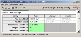
Ya - the slow creep makes it sound like one of the Integral gain parameters (that normally increases with time) and since it's sort of a limiting instead of responsiveness problem I'm thinking it's associated with speed limiting.

If you have a specific set of speed parameters in place, try increasing IntSGain, otherwise reset at least IntSGain to the default below (50).

SLim.png
 
thanks tekletik,

it was indeed the speed limiting settings that I messed around with for the first time up the mountain on the fly.

I stuffed around for 5 mins until I set something to zero I think either the min start speed or the Inst you suggested and finally back to normal. :D

cheers
 
teklektik said:
Very interested in how this works out! :D


me too...iam near finish setup all wires.
the left one is Regen.
The controller has only one cable to setup regen. the manual said 12v input from ebrake for high braking and gnd for low braking.
whatever it means.
i connect the throttle (-) to regen but there starts no regen. With slide recharge regen works. but i dont like it.

anyway... what can be the reason for a flicker of the CA Display?

i made a little video to show. but in this video it flickers only half as in real. i think the cam is here the problem to show realistic flicker.

https://dl.dropboxusercontent.com/u/55508799/ebike/raptor/2014-07-06%2014.32.28.mp4
 
Merlin said:
The controller has only one cable to setup regen. the manual said 12v input from ebrake for high braking and gnd for low braking.
whatever it means.
Seems like it's saying that Gnd is No Regen - but I'm not sure.

Merlin said:
i connect the throttle (-) to regen but there starts no regen.
This would seem to confirm the above guess, but... ?

Merlin said:
With slide recharge regen works. but i dont like it.
Gee - I'm not sure what you are describing here... What is 'slide recharge'?

Merlin said:
anyway... what can be the reason for a flicker of the CA Display?
I don't really know - how were things wired when you recorded the video?
What is the voltage between the regen wire and the controller Gnd with regen not connected to anything?
I'm a little concerned about the manual mentioning 12v as a possible regen voltage and the possibility of a 12v pull-up voltage on the regen wire...

Do you have a link to a manual PDF or a PDF version you can post here? That might help figure this out.
 
slide recharge is starting regen with the throttle.
cruising or accelerate means no regen, closing throttle starts regen.


My CA is wired up:
sorry for that perfect drawing :p

i use 2 shunts because i drive 150 Battery Amps...Each Shunt can Handle 40 continue and 100 Short. So 2 of them fit my needs perfekt.

Some Explaination for this "Picture"...
- The Magura is connected to CAv3
- CA V3 is connected to ONE of the Shunts.
- The Shunts were Parallel soldered (+ / -)
- The 2nd Shunt is not wired up to CA or Throttle/Controller). I use only one (and half the Shunt Setting to 0,5)
- The Keyswitch gets his (+) from Battery
- I use a Antispark Connector (7mm Bullet) from that bullet i have soldered 2 slim awg 24 wires to start controller by keyswitch.
- After that the CA runs all the Time, because he has Power (+) from Shunt/Battery. But it is important to switch the CA with the Keyswitch on/off.
Because legal stuff (starting Modus 1) ;P
- So i opened the shrinktube from 6PIN JST Connector from CAv3 and wired it to the keyswitch.
Everything works like expected. But it flickers. Cant really say if it was the same with CA (+) not wired to Keyswitch.
(But cant imagine).....(+) means (+) right?!

2014-07-07%2000.02.08.jpg


I had my first run today. Unbelivable Accleration and Power. Really nice Throttle. So smooth you an handle 12KW easy.
Next i will try to lower the access time from 200ms to 10ms for the throttle and you can setup the Phase amps on 50% Throttle.
so i think the power will come earlier. Using a Poti for Wattage Limit works also fine. Hope it will do with PAS also good.
atm i havent a pas.(just ordered)

Hope_Br%C3%BCcke.jpg


PINOUT from Controller:

http://endless-sphere.com/forums/viewtopic.php?f=30&t=51485&start=100#p773096


Manual from Website (CD Content) Driver and some PDF inside.

http://www.sabvoton.com/download.html
 
Thanks for the links - although I have to say that the manual is so cryptic as to be almost indecipherable. I do see the setting for 'slide recharge' but the 'electric lock' connection' doesn't seem to have any details - I assume that's where your keyswitch is connected. I didn't see any notations for lock or ebrake voltages - but that could just be me.

I've got nothing for you on this one. Your wiring of the CA looks okay, and I don't see why it should be flickering.
I can't tell in the video - exactly what are you doing that causes it to flicker (I assume it's not just random).
Is this with no regen stuff hooked up or configured?

The only thing I can think to try is to measure the voltage at the controller throttle connection while you turn the throttle or do what do to cause the flicker. You might also hook a meter in-line there and examine the current on the throttle connection to see if it jumps when the throttle is turned - It should be very low - in the neighborhood of 1 ma or less. You might repeat the current test on the (+) power wire to the CA - current should stay around 10-12ma or so.

BTW - you could have wired the CA power up as shown below. This is mentioned in the Guide - the controller (+) doesn't really need to go through the shunt module. But you have it wired already and your approach is perfectly good.

DualExtShuntWiring.png
BTW - the bike looks very cool! :D
 
I was out riding today and observed some odd behavior with my CAV3-mediated control system.

The symptom was a "full power" surge of 1/2 second or less duration. These brief surges would occur at various intervals, from a few seconds to tens of minutes. Since I was out on a long ride I spent a good portion of the time waiting to observe the CA V3 diagnostic screen for when these surges occurred.

Normally when I'm riding in torque assist mode power is limited according to the Aux Pot, so on the diagnostic screen the "W" is uppercase. When these surges occurred the "A" would also go uppercase, and I could see the current pop to a high value. The OUT voltage did NOT change significantly, drifting around 2.1 volts.

At first I thought it might be a loose connection on the Aux Pot wire, so I checked for that and exercised the JST-SM connector in case one of the pins had lost good contact. No change in behavior. The surges still occurred.

Then I watched screen 3-Instantaneous Pedal Assist Summary. When the surges occurred hwt would pop to over 1500 watts, but RPM would read correctly. When I switched to AutoPAS mode, I observed brief drop-outs of assist power. At these moments hwt would be negative. I exercised the Thun 5-pin JST-SM connector, but this made no difference. The surges/drop-outs continued at various random intervals.

I suspect I have a problem with the Thun BB or its wiring. But before I pull the BB (which is a hassle due to the wire being threaded through a hole in my BB shell, which means I need to cut the wire if I intend to completely remove the Thun) I thought I'd post this problem to see if there's something else I should check.

Is there a way to check the Thun BB circuits for faults?

Thanks for your help.

My CAV3 is running with a system voltage between 22 and 30 volts. Attached to the CAV3 are Thun BB, Aux Pot, throttle, and E-brakes. I'm using the following selected CA settings:

SLim -> MaxSpeed = 35 mph
SLim -> StrtSpeed = 0 mph
SLim -> IntSGain = 200
SLim -> PSGain = 0.85 V/mph
SLim -> DSGain = 200

PLim -> MaxCurrent = 45 Amps
PLim -> AGain = 50
PLim -> MaxPower = 1000 Watts
PLim -> WGain = 50

PAS -> PAS Poles = 8
PAS -> DirPlrty = Rev "=5v"
PAS -> StrtThrsh = 30 RPM
PAS -> StopThrsh = 16 RPM
PAS -> PASMode = TorqPAS
PAS -> PASWatts = 1000 Watts
PAS -> MxThrotSpd = 99 mph

Trq -> SensrType = Thun BB
Trq -> TrqScale = -200 Nm/V
Trq -> TrqOffst = 2.45 2.45 V
Trq -> AsstFactr = 8.00 Times
Trq -> AsstStart = +050 Watts
Trq -> AsstAvg = 16

Aux -> Function = Limits
Aux -> ScaleLim = PAS Level
 
cal3thousand said:
mrbill said:
cal3thousand said:
  • #2: I've seen that someone else claim (but they didn't show how) to wire up a hack to access the controllers shunt for charging, eliminating the need for an external shunt.

Any help on this is appreciated

I use my controller's shunt for measuring charge going into the battery.

I do this by running out a pair of wires (+ and -) from the controller's power bus on the controller side of its shunt, then splitting it several times (so that I can hook up chargers in parallel or run other accessories off the ebike battery such as headlight, taillight, USB power port, etc.) and have their draw show up on the CA display. When it comes time to charge the battery I don't need to disconnect anything. Only need to connect my charger to one of these connectors so that current flows backward through the controller's shunt and into the battery.

This photo of the backside of an Infineon/LyenMKII EB312 board shows where I connected the leads.

A couple of points:


  • 1. Any power introduced to the controller after its shunt will not show up on the CA display nor be limited by the controller's internal current limit, although this is not much of a concern unless you're load-testing your motor system with a high-current charger or power supply connected.

    2. I usually leave the charger connected to the controller overnight and because I want the CA to record the re-charge stats, the controller must remain on for the duration. After the battery is charged, there should be no difference in voltage on either side of the controller's shunt. But, because I zero the CA* to ignore the controller's quiescent current draw and the quiescent draw of a couple of power converters connected after the shunt, the CA continues to see an apparent negative current flowing through the shunt for many hours after the battery is charged. This could amount to 1 to 2 Ah overnight. The longer I leave a charger connected in this manner to 'float' a battery following a charging session, the less accurate the Regen Ah display will be. So, unless I disconnect the charger soon after the battery is charged, the CA will show slightly higher Regen Ah than actually occurred.

I find this recharge-measuring capability most useful when I'm doing a quick recharge before a trip or during a trip, when the recharge may only be partial.

*One could connect a charger in this manner without a battery connected and then zero the CA so that when operating normally (without the charger connected) the CA shows all current drawn from the battery, including quiescent current from controller and any accessory converters.
mrbill,

This is helpful and I much appreciate it.

So this is what I'm reading: I only need to run leads off the negative and positive traces (aka Power Bus; <-- learned something today) and can also parallel off of them for multiple inputs.

To me, this seems like a modification that should be done to all CA-kitted controllers to allow charge monitoring. At least, I know what I'm doing with all my controllers. I will primarily be using the CA to monitor charge with bulk chargers/PSUs on the road so I can cut charge when I'm satisfied.

I wonder how this effects the lifetime/cumulative stats of the CA?

I discussed similar in thread "Can CAv3 read Charging Current as Regen" with amberwolf, might be of help http://www.endless-sphere.com/forums/viewtopic.php?f=2&t=57034 . Can get tricky depending on BMS i guess
 
maramusa said:
I discussed similar in thread "Can CAv3 read Charging Current as Regen" with amberwolf, might be of help http://www.endless-sphere.com/forums/viewtopic.php?f=2&t=57034 . Can get tricky depending on BMS i guess

Thanks for your followup.

The advice I gave above is appropriate for batteries that charge and discharge through the same leads, batteries that contain what are sometimes called "2-wire" type BMS. If your batteries have separate charge and discharge circuits, then you should read the above thread for other options to avoid damaging your batteries or BMS systems.

Btw, I strongly prefer the 2-wire type BMS as this simplifies wiring and the charging and discharging of multiple batteries, either in series or parallel.
 
Hi everyone,

One thing i wouldnt mind knowing about the set up is Tyre "Tire" size. Maybe there is already something on this in the 93 Pages but i couldnt find it but i did miss the odd few pages trying to keep up.

Maybe we could all put our sizes down for the CA set up because i wouldnt mind knowing what they are for future reference if i change my tyres over in the future.

When setting up my CAV3 with my rear wheel of 24" and running a 2.5 wide maxxis Hookworms at 45psi i got a tyre size of 2005mm to set up the CA and i was wondering what everyone else got with there 24" tyres and other sizes like a 26" rim and so on with what size tyre was used like a 1.75 or 2.125 and so on.

Or should this go in the F A Q Section ?
 
Hi guys!
Just got my lovely new CA V3 DPS and there are so many settings its awesome with confusion haha
I have a MAC 9fet 4110 controller and for the moment, my throttle isn't connected to the CA. I wired the throttle directly to the throttle wires on the controller.
The speed is very slow unloaded when using full throttle, but when I unplug the controller, the speed increases very high to where it used to reach before installing the CA.

I was wondering, in the SETUP THROTTLE IN
do I select "Pass Thru, Current A, Speed kph, Power W, Off 0V, WOT 0V ??
Should I be running the throttle through the CA instead? Its a normal 3 wire Wuxing half throttle.

Also, my shunt value is 2.09..must I input this under SETUP Calibration? The stock setting is 1.0

Thanks a lot!
 
Back
Top