parabellum
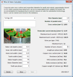
1 MW
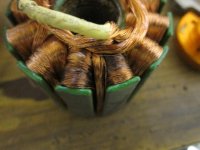
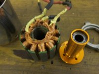
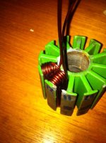
I do not think removing shaft bearings will help to reveal winding. Btw. why are the windings soldered to the phase wires? In D the winding ends usually go out the motor as phase wires and are soldered outside, in Y 3 winding ends are soldered and buried inside and other 3 go out. Makes little sense to have them solder connected inside, just adding heat and failure mods.Bazaki said:I dissambled the motor many times, but It seems to be impossible to remove the skirt bearing and housing like at the picture, I will try your number 4, I did not remove the shaft bearing.
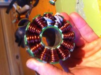
I have to get to the point where the windings are soldered to the phase wires, I need to waterproof the whole stator. I plasti dipped it many times but I can't get it waterproof behind the skirt bearing housing.
Any idea's how to waterproof this ? Epoxy is a bit risky because it permanent, and plasti dip is a bit weak.
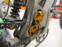
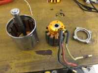
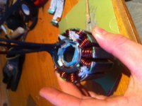
Skirt bearing can be pressed very tight on this aluminum stator peas we can observe on the picture. I usually just hit with the hammer on outstanding ears of the outer skirt bearing fixture in sequence to not incline the bearing to much.
Hope it makes any sense.