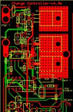
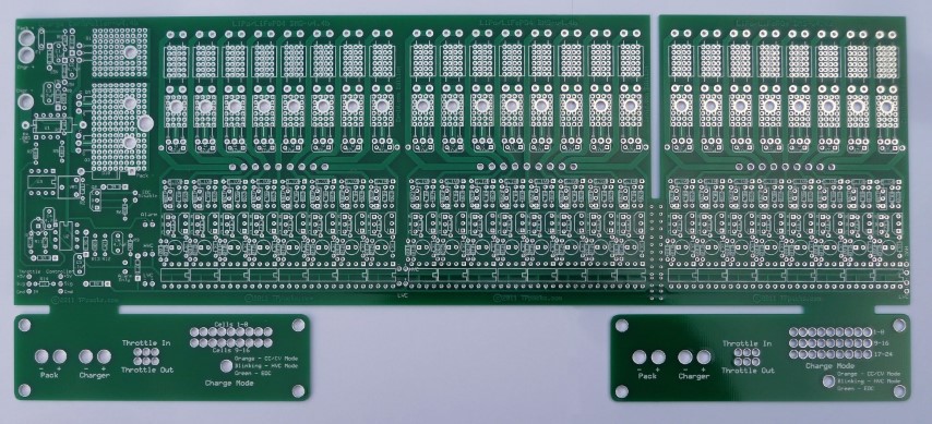
"Zephyr" - Finally, the "v4" Fechter/Goodrum/Hecker BMS...

midwest mayhem said:
I've done this without any cells connected and the master LED faintly lights up (red, I believe) around 8v, but goes up to 20v without drawing any current registered on the power supply. The board passes all the other tests. Is this bad or can I ignore it as long as everything else functions correctly?

Take it up to 20v and measure the voltage on the main FET gate (probe the two outside legs carefully).
 
I've had queries about substitutions for the now obsolete 512-FAN431LZXA. I already PMed Richard about this because I need spares for my own Zephyr unit.

Here is his response:
fechter said:
There are tons of substitutes. Any "431" in a TO-92 package will work. There may be slight variations between flavors. I found some versions will have a slightly different voltage for the same divider resistors. It's nearly impossible to tell without testing. Variations are generally less than 5%.
We used the FAN431 in many previous boards.

Here are a few possible subs, I only listed the 1% accuracy versions. More accurate versions are more expensive, but the accuracy of the resistors will be limiting. 1% versions are good enough.

512-FAN431AZXA
512-KA431AZTA
595-TL431AILPM
595-TL431AILPME3
511-TL431ACZ
512-KA431AZBU
 
fechter said:
On some versions of the board, there were holes for the diode that placed it between the two main FETs. You can put it there or on the side, whatever is easier. It should look more or less like this:

file.php
The diode addition Richard describes has now been incorporated into the 4.4b version of the board.

4.4b TVS diode v2.jpg
 
yopappamon said:
I'm building a 48 cell pack for a ev car (Chevy volt cells).

Is there any reason I couldn't use 2 -24 cell sets of this BMS?
Richard says that each board is suitable for "5s to 24s" (as specced in the shop). I take from that that it can handle a minimum of 5s.
 
I'll have to think about that. There isn't a built in provision for ganging more than one board together, but it is possible. I'll take a look at it and report back. I think it will be pretty easy to do.

The minimum cell count is 5, to provide the necessary 12v for the charge control FETs.
 
Ok, for more than 24 cells, there is a provision for this. You would make one board the "master" and populate all the parts. The next board(s) would only need the cell circuit parts installed for the number of cells needed. The control portion can be left empty, as can any cell circuits that are not used. People who bought a 24s board and only used 16, for example, would have an empty 8s chunk that could be cut off and used to extend another board.

On the end of the board, and at each 8s gap, there are 4 pads labeled LVC+, LVC-, HVC+ and HVC-. Simply install wires between board sections to these 4 terminals and you can extend the number of cells to as many as you want. Eventually you would reach a point where the creepage distance becomes an issue where the voltage between adjacent traces gets high enough that arcing might be possible. Conformal coating potting will extend this. I think you'd be OK up to about 100 series cells as long as the board is protected against moisture and contamination.
 
fechter said:
I think you'd be OK up to about 100 series cells as long as the board is protected against moisture and contamination.
Are you saying it could theoretically go to 100s? Wow!

What's this limit based on? I thought the FETs would get toasted with that much wallop!
 
Zenid said:
fechter said:
I think you'd be OK up to about 100 series cells as long as the board is protected against moisture and contamination.
Are you saying it could theoretically go to 100s? Wow!

What's this limit based on? I thought the FETs would get toasted with that much wallop!

OK, I should clarify that. Yes, you're right, the FET would get toasted unless you had one with the right rating but the optos can be chained together until the voltage gets scary high. The voltage regulator also runs off the full pack voltage and could possilby overheat beyond 24s, but you could break this connection at the fuse and tap the pack at 24s or less to keep it happy. This would result in a slight imbalance but would probably work OK. Alternately if there was a separate 12v supply for the charge control, you could power it that way. The drain is quite low.
 
yopappamon said:
I'm building a 48 cell pack for a ev car (Chevy volt cells).

Is there any reason I couldn't use 2 -24 cell sets of this BMS?
So, basically, Richard, the answer to yopappamon's question about daisy-chaining up to 48s is yes, but a minor mod needs to be made to keep the voltage regulator powered from 24s, right? I'm guessing cutting a track somewhere and adding a crosswire...

Can the control circuit FETs take it, or does he need different rated ones?
 
To clarify, I am not going to use the charger portion of the board. I am only going to use the cell balancing and take to lvc and hvc signals to my own circuits. Lvc will probably just sound a warning and the hvc may shut off the charger, depends on if I get a new charger capable of that or not.

So I will end up with 48s 2p ( actually 6p but that's internal to the pack, I only need to balance the 2p). So I need 4 of the 24 cell boards. I will parallel the hvc and lvc outputs to a relay or whatever(tbd).
 
yopappamon said:
To clarify, I am not going to use the charger portion of the board. I am only going to use the cell balancing and take to lvc and hvc signals to my own circuits. Lvc will probably just sound a warning and the hvc may shut off the charger, depends on if I get a new charger capable of that or not.

So I will end up with 48s 2p ( actually 6p but that's internal to the pack, I only need to balance the 2p). So I need 4 of the 24 cell boards. I will parallel the hvc and lvc outputs to a relay or whatever(tbd).
Ah I see! That's okay then.
 
if it is 48S2P you should only need two boards. they are 24S each i think. use the lowest resistance value shunt resistors that the transistors can handle to keep the balancing current high. maybe even wire a fan on a thermostat switch from 12V along with the 12V for the control circuitry. use a case to direct the airflow over the shunt resistors and even glue them to the cover for a heat sink like richard mentioned earlier. what voltage will you use for balancing? 4.17V?

i wish i could figure out how to use the D131 to control larger shunt transistors so that i could use a slave board carrying some big power resistors to increase balancing current. but it is getting really hard to solder now. so i could not build one of these boards.
 
yopappamon said:
I could use 2 boards if the 2 parallel packs had each cell paralleled. But the way the packs are, only the groups are parallel. I suppose I could combine the balance leads so I only need two boards. Something to think about.

having paired boards would increase balancing current but you may be able to do that by just using really big power resistors and finding a way to deal with the heat.

i forgot how this is already 3P so you would be going to 6P. my 21S lipo pack is 7P 44Ah wide and i use two D131 balancing boards, 350mA for both of them.
 
dnmun said:
i wish i could figure out how to use the D131 to control larger shunt transistors so that i could use a slave board carrying some big power resistors to increase balancing current. but it is getting really hard to solder now. so i could not build one of these boards.

I designed a 'balance booster' board that attaches to the existing shunt resistors (makes soldering somewhat easier). the booster board can be attached with a connector and removed when not needed. Not built or tested yet, but this is pretty simple. This should work with most Bestech or Ping (Signalab) style boards. Depending on how much heat you can dissipate, it should be relatively easy to get 1A of balance current.

Zenid said:
yopappamon said:
I'm building a 48 cell pack for a ev car (Chevy volt cells).

Is there any reason I couldn't use 2 -24 cell sets of this BMS?
So, basically, Richard, the answer to yopappamon's question about daisy-chaining up to 48s is yes, but a minor mod needs to be made to keep the voltage regulator powered from 24s, right? I'm guessing cutting a track somewhere and adding a crosswire...

Can the control circuit FETs take it, or does he need different rated ones?

Yopappamon is OK since he is using an external charge control. Many large chargers have a thermistor input that could be tied to the HVC to control the charge.

With the Zephyr board, the FET really only 'sees' the difference in voltage between the charger and pack, so the voltage rating of the FET could be less than the pack voltage. If the charger is not powered when you connect to the BMS, the pack will try to charge the output caps of the charger and you could get a spark, but due to the body diode in the FET, they won't be exposed to more than a volt or so during this connection.

If the pack voltage exceeds the voltage rating of the FET, the TVS diode is highly recommended. If the charger was on, but the pack was disconnected from the BMS, there the voltage rating could be exceeded. I think this would only happen during building/testing, so not generally a problem.
 
I've put together shared project forms that can be used to order the parts.

Zephyr 4.1b LiFePO4 24s components order form:
http://www.mouser.com/ProjectManager/ProjectDetail.aspx?AccessID=7b8daff5cc

Zephyr 4.1b LiPO 24s components order form:

http://www.mouser.com/ProjectManager/ProjectDetail.aspx?AccessID=d4c8fbb68a

The current versions are for 24s, but I will produce 16s versions as time permits (for now, you can just change line items as required). Now we can just update the mouser order form (or shopping cart) to deal with any obsolete parts or substitutions, instead of everybody individually doing their own identical orders. Hopefully this will make things a lot easier.

N.B: This is brand new so PLEASE CHECK before ordering!
 
Hey There, first things first.... Ive had my v4.4 board for a little while now, and just now getting back into the project, but its been great so far!!! Halfway through the assembly too :)
Thanks again!!!

Just a quick question though, Is there anyway to add the ability show the cell voltages on an LCD or something to that extent?

It would be awesome for the ability to have an Arduino, RPI or other tech that would allow the ability to query the voltages of each cell and total pack voltages...

My pack is made up of 12x 5MAH Turnigy 20C 6S Packs. They are wired up as: 6S x4 then x3 so its a 24S4P 20AMP/HR Pack
 
eBikeJunkie said:
Just a quick question though, Is there anyway to add the ability show the cell voltages on an LCD or something to that extent?

It would be awesome for the ability to have an Arduino, RPI or other tech that would allow the ability to query the voltages of each cell and total pack voltages...

My pack is made up of 12x 5MAH Turnigy 20C 6S Packs. They are wired up as: 6S x4 then x3 so its a 24S4P 20AMP/HR Pack
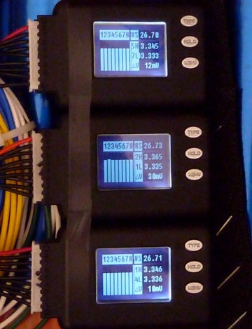
I just knocked something together out of 3 CellLogs for mine:
http://zenid10.wordpress.com/2011/09/05/monitoring-pack-cell-voltages/

c7b-n-1600x1200.jpg
 
fechter said:
midwest mayhem said:
I've done this without any cells connected and the master LED faintly lights up (red, I believe) around 8v, but goes up to 20v without drawing any current registered on the power supply. The board passes all the other tests. Is this bad or can I ignore it as long as everything else functions correctly?

Take it up to 20v and measure the voltage on the main FET gate (probe the two outside legs carefully).

Never did this test but finally got everything together and I think it works! Charging a 15Ah LiFePO4 Headway pack with two 54v Meanwell's (max voltage without load is 119 volts).

Only concern is the LED for the first cell seems to be on when the others are off and flashing opposite of the others in the final "pulse" (I think that's the final one) charging stage.

It took a while to balance the first time around and I wasn't sure if it was going to work (one cell didn't seem to charge) but eventually all the shunt LEDs came on. I was confused that it stayed orange (CC/CV mode) for so long without seeming to do anything then turn red and have shunts come on, then go back orange for a long while.

Then the all the shunts came on bright and stayed on pretty much continuous with a brief flash of indicator LED every 2 seconds. Shunts got pretty hot, so I turned down charger voltage. Had to unplug charger a few times while adjusting because the indicator started flashing all 3 colors so I guessed I had to reset it. Then played with EOC adjustment, lights flashed a lot, then indicator turned green!

Below are two videos, one of the beginning of charge and other at the end. In both you can see the issue with the first cell's LED. The only thing different about this cell is I don't have a tap wire, I jumped it to the pack negative like Zenid did. Could this be the issue?

tl;dr I think it works but the first cell LED is wonky.

[youtube]fihS-uexPEw[/youtube]

[youtube]mmklWUkaCwg[/youtube]

Thanks to everyone who's been involved in this project! I had no previous experience with this sort of thing (college mechanical engineering student), but was confident with the resources available to me I could figure it out.
 
midwest mayhem said:
fechter said:
midwest mayhem said:
I've done this without any cells connected and the master LED faintly lights up (red, I believe) around 8v, but goes up to 20v without drawing any current registered on the power supply. The board passes all the other tests. Is this bad or can I ignore it as long as everything else functions correctly?

Take it up to 20v and measure the voltage on the main FET gate (probe the two outside legs carefully).

Never did this test but finally got everything together and I think it works! Charging a 15Ah LiFePO4 Headway pack with two 54v Meanwell's (max voltage without load is 119 volts).

Only concern is the LED for the first cell seems to be on when the others are off and flashing opposite of the others in the final "pulse" (I think that's the final one) charging stage.

It took a while to balance the first time around and I wasn't sure if it was going to work (one cell didn't seem to charge) but eventually all the shunt LEDs came on. I was confused that it stayed orange (CC/CV mode) for so long without seeming to do anything then turn red and have shunts come on, then go back orange for a long while.

Then the all the shunts came on bright and stayed on pretty much continuous with a brief flash of indicator LED every 2 seconds. Shunts got pretty hot, so I turned down charger voltage. Had to unplug charger a few times while adjusting because the indicator started flashing all 3 colors so I guessed I had to reset it. Then played with EOC adjustment, lights flashed a lot, then indicator turned green!

Below are two videos, one of the beginning of charge and other at the end. In both you can see the issue with the first cell's LED. The only thing different about this cell is I don't have a tap wire, I jumped it to the pack negative like Zenid did. Could this be the issue?

tl;dr I think it works but the first cell LED is wonky.

Thanks to everyone who's been involved in this project! I had no previous experience with this sort of thing (college mechanical engineering student), but was confident with the resources available to me I could figure it out.

Mate, If I see it correctly on the vids you are running 16s LiFePo (so the following is based on that assumption). Charging voltage: 16 * 3.65V is 58.4V; you are feeding it with 119V!
Congrats, you successfully stress-tested the Zephyr :D
Put the Meanwells in parallel if you need the amps for charging. Check the threads around here before you do that. For the moment, try adjusting one to a moderate level like 3.60V/cell = 57.6V and try again.
HTH
 
Back
Top