A123 20AHr Pouch Cell Battery Build & Info Thread

So last night I did a trip with my 24s battery I built in this thread. Unfortunately I only could pull 14ah from the battery after doing about 32 miles.

So right now I am using my 306b to charge/discharge each cell to see which one or ones are weak. Could not think of any other way to determine.

Luckily I have about 10+ extra cells that I have tested capacity in the past.

Also nice looking build EVil.
 
ohzee said:
So right now I am using my 306b to charge/discharge each cell to see which one or ones are weak. Could not think of any other way to determine
Well, yea, you need to do a capacity test. The various balance chargers do that by logic chip, but it can be done rather crudely manually. Its charge-discharge-charge. Charge to optimal max, in the order of 3.6V. Discharge with a monitor of some kind, a multimeter or celllogs so during discharge you can see voltage drop. My 12S1P AMP20 pack has a balance harness attached and two celllogs, so I see the whole curve. My approach is the rack up the front wheel (Heinzmann 500watt front hub motor) and duct tape the throttle on. At max throttle, it'll take about two hours to discharge the pack to interesting levels. I'm no longer fearful of a near-full discharge, given how robust the A123 nanophosphate is. See what happens to each cell on discharge. Then its easy to spot the weak one. And with a stash, replace it if need be. Since I depleted my stash, that's not an option for me, but with 10 in the box, you're good.
 
Thanks arkmundi - that's what I am doing now. I have always been fearful to have my 5404 at full power unattended , but it would be a good way to watch under real conditions.
Thanks for the idea. Good thing about the yuba it's easy to wedge a couple milk crates under the side racks.

I noticed last winter I had reduced capacity , but I just figured it was the cold weather ;\
 
500 cycles - 4132ah - 6421 miles
These my A123 20ah 24s pack. Balance charged each time to 3.59v. It's dosn't have the same pep as when new, but works fine. A little heavy. I run at 30amps with a 2810 hibread a 9c stator in a Paul muxus hub. Anyone else ?
 
Still going! 12S A123Amp 20 split pack. Balance charged every time for almost 2 years of regular use (3-5x per week) 20 mile runs. One cell is very slow to balance on the Thunder 12 20, and I have 2 extra cells from early Victpower full tabs.
otherDoc
 
Hmmm........maybe I spoke too soon. About 2 miles into our Sunday 20 miler my trike just quit. Enough power left to light the Magicshine but no motive power. The little LCD from the S12S controller would not restart. Luckily, we have a towrope in my wife's basket, (a dead innertube and 10 ft poly rope.) Smooth ride home! Troubleshooting now. Still power screen would not turn on, and all 12 cells read 3.35+/-. On the charger now. Stay tuned. This has never happened before but I was off the bike about 10 days with a sprained ankle. Charged 10 days ago.
otherDoc
Whoops! Charger just beeped going to balance after only 20 min charge.
 
And the culprit is...................The Fuse, TaDa! 30 am fuse blew. Only happened one other time. I think the S12S is around 22 amps limit, but not sure. I have seen 30 before going up some of our 5% hills, but no blow, till now. The auto store only had 30's, so I may double them if it keeps happening. Took me over an hour to go through all the wiring and do a quickie battery draw test. Crude! I used 2 battery medics and locked the trike against the wall, then turned up the power a bit. I should have realized I had bypassed the fuse part, but didn't till later. Old age slows the memory. Battery is perfect.
otherDoc


docnjoj said:
Hmmm........maybe I spoke too soon. About 2 miles into our Sunday 20 miler my trike just quit. Enough power left to light the Magicshine but no motive power. The little LCD from the S12S controller would not restart. Luckily, we have a towrope in my wife's basket, (a dead innertube and 10 ft poly rope.) Smooth ride home! Troubleshooting now. Still power screen would not turn on, and all 12 cells read 3.35+/-. On the charger now. Stay tuned. This has never happened before but I was off the bike about 10 days with a sprained ankle. Charged 10 days ago.
otherDoc
Whoops! Charger just beeped going to balance after only 20 min charge.
 
arkmundi said:
EVil said:
Thought I'd toss a few pics of my pack build up.
I used the compression method. 12S per pack and two packs on the bike.... The tabs are compressed separately from the cell bodies. The two lexan plates compress the cell bodies and the tabs are compressed by a quasi-floating end plate. The cell tabs are connected with Alum bars and isolated from one another with nylon plates. There are screws in the top of each of the aluminum bars so that I can charge the cells individually - each cell has it's own dedicated charger...
Superb design & build. Kudos. What are using for dedicated charger? Thanks.

I designed/built my own.

2013-04-11 10.47.05.jpg

Its basically a flyback converter married to a buck converter that operates in constant current/constant voltage with a maximum charge rate of 5A (72kHz operating frequency). So, you plug one end into the wall outlet, hook a cell to the output, and let it do it's thing. I was running at 6A charge rate but I could tell (without forced cooling) they weren't going to last long. The rectifying diodes on the secondary side (as well as the snubber circuit) were getting a little warm :)

So each cell in the pack gets connected to its own individual charger - 24 cells means I need 24 of these chargers. The advantage is that I never need to balance cells - each charger makes sure its attached cell always gets charged to 3.6 V before indicating (via LED) that the charge is complete!
 
arkmundi said:
ohzee said:
So right now I am using my 306b to charge/discharge each cell to see which one or ones are weak. Could not think of any other way to determine
Well, yea, you need to do a capacity test. The various balance chargers do that by logic chip, but it can be done rather crudely manually. Its charge-discharge-charge. Charge to optimal max, in the order of 3.6V. Discharge with a monitor of some kind, a multimeter or celllogs so during discharge you can see voltage drop. My 12S1P AMP20 pack has a balance harness attached and two celllogs, so I see the whole curve. My approach is the rack up the front wheel (Heinzmann 500watt front hub motor) and duct tape the throttle on. At max throttle, it'll take about two hours to discharge the pack to interesting levels. I'm no longer fearful of a near-full discharge, given how robust the A123 nanophosphate is. See what happens to each cell on discharge. Then its easy to spot the weak one. And with a stash, replace it if need be. Since I depleted my stash, that's not an option for me, but with 10 in the box, you're good.

So 2 weeks later of pretty much daily charging/discharging/charging my 24 cells I have determined that they are all indeed fine. I get right around 18ah capacity give or take a small variation on each cell. So that's good and bad news.. Good news I don't need to replace any cells. Bad news that my BMS may need to be replaced.

So I charged my batteries via the BMS prior to my charge/discharge/charge and what I have noticed is that he cells near 20+ are taking up to 1.5 additional Ah
from my 306b before doing a capacity test.

So I figure my options are as follows. Also this is a EV Assemble high discharge BMS.

- Add taps to my 24s battery so I can charge 6s at a time with my 306b while balancing at the same time and use the BMS for discharge.
- Balance the cells with my 306b once and then use the BMS to charge/discharge and see if capacity is normal.
- Break out the founding power 24s BMS I bought some time ago and give it a try. It has just been sitting on the shelf for such an occasion.

Anyway wanted to follow up.

As a bit of entertainment I did put the bike on blocks & ran the throttle full open to test capacity on a 20s a123 battery I also have which was fine for an hour , but
then I came back and the motor was not moving & hot as sh1t. Quickly disconnected & directed a couple fans at the 5404 motor to cool it down. Spent last weekend
taking the thing apart. I managed to melt the internal hall wires along with some of the solder. Good part of this is none of the halls failed so once I re-spliced all my
wires and put it back together I was back in business. Will not do that again and had a feeling it was a bad idea anyway.. Live and learn. Hoping I did not damage the
magnets to much. Need a CA 3 with the temp sensor option to shut the motor down. Going to do that as I near completion of the phasor.
 
Ah, what we sometimes go through. Sorry to hear about the melt down. I've heard it said that if you mismatch to FET to your motor, you can over-amp it and melt something. But you're my first encounter with someone that has actually happened to. You may want to revisit the spec of your controller. A BMS on charge with a balance charger is a waste, yea. One or the other, but not both. Best!
 
EVil said:
each cell has it's own dedicated charger...
I designed/built my own.

[/quote]
Nice build mate.
Do you think a 50A could be made in a small package too, maybe higher frequency?
That would be the holy grail of A123/20 charging.
 
megacycle said:
Nice build mate.
Do you think a 50A could be made in a small package too, maybe higher frequency?
That would be the holy grail of A123/20 charging.

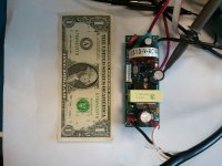
The old standard was to single-cell charge with a bank of DC-DC converters. I used 20a Vicor dc-dc converters to build a 16 cell SSC bank in '09, (5) of them would fit on a dollar bill so they are pretty small. You probably could find 50a comverters, but since that would be about 200w/cell, in the US you could only charge 9 cells at a time from a 110v outlet.

http://endless-sphere.com/forums/viewtopic.php?f=34&t=8012&hilit=Canev&start=100#p139045

-JD
 
oatnet said:
The old standard was to single-cell charge with a bank of DC-DC converters.
Thanks oatnet, there are some available, though might have to take out another mortgage :cry:
Might go over to trying a multi individual charger like a BC168. and parallel that across the 3kW meanwell I've got.
Hoping to balance and at the same time bulk.
Keeping up with large format out of balance, could it work, or all my senses get a sudden shock :cry: ?
 
megacycle said:
EVil said:
each cell has it's own dedicated charger...
I designed/built my own.
Nice build mate.
Do you think a 50A could be made in a small package too, maybe higher frequency?
That would be the holy grail of A123/20 charging.[/quote]

Even if you could increase the switching frequency to something ungodly practical, try finding a 50A (or higher to ensure you stay out of saturation) off-the-shelf inductor that has a relatively small footprint...
 
oatnet said:
megacycle said:
Nice build mate.
Do you think a 50A could be made in a small package too, maybe higher frequency?
That would be the holy grail of A123/20 charging.

The old standard was to single-cell charge with a bank of DC-DC converters. I used 20a Vicor dc-dc converters to build a 16 cell SSC bank in '09, (5) of them would fit on a dollar bill so they are pretty small. You probably could find 50a comverters, but since that would be about 200w/cell, in the US you could only charge 9 cells at a time from a 110v outlet.

http://endless-sphere.com/forums/viewtopic.php?f=34&t=8012&hilit=Canev&start=100#p139045

-JD


That's an extremely nice build!

I'm sure, even back then, they didn't give those DC-DC converters away :wink: I did a little hunting and found that one 20A module is a hair over $100 - and then you still need to support them with an AC-DC converter. Whew! Yeah, I can see why megacycle jokingly mentioned having to take out a mortgage.
 
EVil said:
That's an extremely nice build!

I'm sure, even back then, they didn't give those DC-DC converters away :wink: I did a little hunting and found that one 20A module is a hair over $100 - and then you still need to support them with an AC-DC converter. Whew! Yeah, I can see why megacycle jokingly mentioned having to take out a mortgage.

Thanks :D - though hindsight tells me the bus was more of a platform for experiments than a formal build. The street-legal Dune Buggy in my signature, using the same motor/controller from the camper, is more of a real build - and using a123 factory modules to boot!

$100 each sounds like retail pricing :shock: - according to my spreadsheet, I bought (25) of those DC-DC converters here on E:S for $200 including shipping and PayPal, so $8 each delivered.

The Vicor "megapack" power supplies I use to power the SCC bank, as well as bulk charge from 12v to 175v, I buy on eBay for $50-$75 depending on which modules are installed. These PSUs have 8 slots which can be populated with a wide range of cards from 3v to 48v, and the cards I have used can be put in series for higher voltage, or paralleled for higher amps. Dr Bass pointed me at the MegaPacks in '08 and they have serviced ALL my LifePO4 charging needs ever since.

It might take some time, but if you scour eBay and the for sale forums here you can probably come up with an equivalent deal. :D

-JD
 
megacycle said:
Hoping to balance and at the same time bulk.

Not sure how you mean this. If you mean having having Single cell chargers running at the same time as the bulk charge, no balancing can occur as the bulk charge side will continue pumping amps when theoretically the SCC can't push more current into the cell. Interesting side note - I think it was Fechter who did the SCC testing that found that most of the current was going through the first and last cells, and very little goes through the balance wires unless me cell is dramatically out of balance.

I bulk charge most of the time, and balance charge quarterly or when I know I am going to have an extremely deep discharge. I size my packs larger than I need so my discharges end up shallower, like 60% DOD. This gives me emergency range, the low DOD extends the life of my packs, and even if a cell were 10% out of balance, a 70% DOD on the pack would have that cell at a safe 80% DOD. My a123 seems to stay pretty close to balance though, I can't imagine one of these cells getting 10% out of balance; I have seen more drift with cheaper chemistries like Headways and T-sky/CALB etc.

-JD
 
oatnet said:
I bulk charge most of the time, and balance charge quarterly or when I know I am going to have an extremely deep discharge. I size my packs larger than I need so my discharges end up shallower, like 60% DOD. This gives me emergency range, the low DOD extends the life of my packs, and even if a cell were 10% out of sew, a 70% DOD on the pack would have that cell at a safe 80% DOD. My a123 seems to stay pretty close to balance though, I can't imagine one of these cells getting 10% out of balance; I have seen more drift with cheaper chemistries like Headways and T-sky/CALB etc.
-JD
Thanks for that.
When I got my cells from A123RC, they ended up a mixed bag of Korean & US :cry: they have a tendency to drift apart early in the charge, though I am hitting them at 4C at the outset.
The first one or two to hit the wall will think about 4V if i did'nt curtail and have to start an individual power resistor bleed even 20W resistor can't keep up with outabalance.
I want to have the facility to fast charge from convenience outlets :wink: on the fly.
As I want to build a touring bike.
 
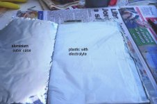
I opened up an a123 20ah cell today, is anyone interested of pics of the internals? if so i'll post some in this thread
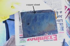
It was a cell gone 'soft' , the aluminium layers black coating were in good condition, the copper layers black deposit was not in good condition,
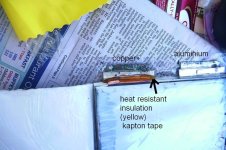
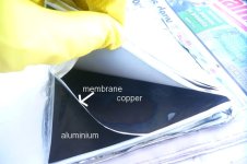
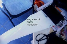
some discoloration and peeling of black layer off the copper. Its pretty much just made of alternating layers of aluminium and copper ( one has graphite coating the other iron phosphate .....cant remember which has which), the alternating layers of cu/al are separated by a plastic membrane which is wet with electrolyte. Each layer of aluminium is spot welded below the tab ( not normally visible), same with the copper layers. Its a good layout as none of the metal layers are bent/rolled or folded as in some types of cells. Underneath the plastic outer pouch the cells are wrapped in a layer of the electroytic membrane.
The outer pouch does not shrink when hit with a heat gun, seems to be resistant to high temp.
 
pics of internals of a123 20ah cell
the cell was used without pressure on the pack, the copper sheets have carbon( graphite?) layer on each side, in this cell
the graphite layer is badly damaged, I'm guessing from lack of pressure between layers.
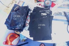
The aluminium sheets have black deposit on them, in very good condition, thats the lithium iron phosphate layer,
so can say that the weakness of the cells appears to be degradation of the carbon layer on the copper sheets.
There are 24 ( 25?) copper sheets and 24 aluminium sheets , each separated by a plastic membrane ( one long sheet) which has electrolyte in it which is folded inbetween the alternating sheets of cu and al.
Each individual sheet of copper or aluminium is spot welded to the tabs. The copper tab has kapton tape to stop it shorting to the innner side of the mylar type outer case. Aluminium tab has no insulation kapton tape.
a123 1.jpg
a123 2.jpg
a123 3.jpg
a123 4.jpg
a123 5.jpg
a123 6.jpg
a123 7.jpg
a123 8.jpg
a123 9.jpg
View attachment 1
a123 11.jpg
 
How much current did this cell have to deliver in its life? There appear to have been pretty serious concentration gradients for current inside the cell. This would be from the lack of compression. What is the lowest voltage the cell ever settled at prior to teardown?
 
only 20amps on ebike in 48v pack,
lowest voltage was 2.4 v
that was voltage when pack was opened up
I think the difference between hard cells and soft cells will be when the graphite layer on
the copper starts to go off, was surprised just how good the iron phosphate layers held up.
They were pretty much unblemished ( iron phosphate layer), the graphite had starting peeling off the copper in places.
When you get some electrolyte starts to be visible from the outside of the pack ( grey bubbles along seams), it looks like that
is due to breakdown of the mylar outer skin, not due to contact with copper or aluminium plates. The inner surface of the mylar pouch appears to have electrical contact with the plastic membrane, first layer under the plastic separator membrane is copper.
Innerside of mylar pouch has no iron phosphate coating, but possibly a very thin plastic coating ( not sure on that)so should play no role in battery capacity, but may hold some charge or at least a conductive path, so cells with cut down tabs and mylar removed to make tabs longer might short from mylar pouch to copper tab ( a bit of silicone seams to solve that issue)
 
Back
Top