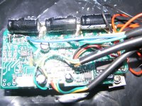
Version 2 Crystalyte Controller information

thanks for that, intriguing, how do you reconcile higher amps in motor, with power out cant be bigger than power in?
also you think in future will be able to play with the higher amps in motor via programming controller chips?
my knowledge on inductance very poor i'm afraid I really dont understand how the inductance is allowing current to flow for a longer period ( any chance of a quick lesson on that??)
freewheel diode would be the inbuit diodes in the fets?
 
found some basic info on inductance, I'll do some reading up on it
http://electronics.howstuffworks.com/inductor1.htm
 
this is interesting, just reading that an inductor ( the motor in this case ) and a capacitor ( the big and small caps protecting the fets) will set up an oscillating circuit.
http://electronics.howstuffworks.com/oscillator2.htm
Has anyone picked up these oscillations on an oscilliscope? I remember fetcher also mentioning oscillations by only having one driver resistor for a fet pair ( as in the V2) might also be due to inductor/capacitor setting up oscillations.
Also I see there is a formula for back emf so you could work out max back emf expected and would be able to predict what voltage caps needed for a given motor running on a given voltage/amps ( seems there is a constant in that formula might be hard to get that value though)
 
bmc 500watt first road test using v2 35amp 48volt
rim size just under 16" ( 15.5" outer dia) odd tyre used
top speed two passengers with 4 lots sla 14ahr batts approx 45km/hr ( 3 wheel vehicle)
hill climbing ability: pretty much anything!!
thanks wayne in south africa for testing
in 26" rim would give 26/15.5*45 = 75km/hr ( wind resistance will reduce top speed though)
26" rim testing hopefully soon, will post some results on torque/top speed when done, 86volt testing some time off still
 
sorry top speed in 15.5" rim was 40km/hr on 48v v2 with bmc500
makes 67km/hr in 26" rim ( yet to be tested)
 
The7 said:
b)If so, at 50kmh top speed on flat (about 41% of no-load speed), the 3 wheeler is limited by the battery current limit of 35A.
The motor current could be about 2.4 times of the battery current (about 85 A).
And it will cause an high current ripple in these 100V capacitors (order of 85A)

c) If so, at 79kmh top speed on slightly downhill ( about 65% of no-load speed), the 3 wheeler is also limited by the battery current limit of 35A.
The motor current could be about 1.5 times the battery current (about 53A).
And it will cause an high current ripple in these 100V capacitors (order of 53A).


I'm curious to know what formulas or info you used to conclude 2.4 x or 1.5 x battery current. I have an electronics engineering degree from 1984, but little recent experience, especially with 3 phase motors.

Inductor is sort of like a backwards capacitor. But I don't see how to get more than battery voltage with a batt and a capacitor, unless it's somehow switched between multiple capacitors like in an AC voltage multiplying circuit.


I'm looking to try and build an electric brake for my 404 on a XLyte 72v, 20a, PF. In theory I think it's as simple as one 100w light bulb and a switch on 2 phase wires. Ideally, 3 bulbs and a DPST push button for 3 phase smoothness. Add more lights and a dimmer for variable braking. (Could it REALLY be that simple?) Add a 3phase bridge rectifier and some other stuff for batt regen.

I'm presuming that using this e-brake will waste power if brake is on and throttle is on at same time, but nothing will probably blow. Of course, best to use with throttle off, with a brake switch.
 
mikereidis said:
The7 said:
b)If so, at 50kmh top speed on flat (about 41% of no-load speed), the 3 wheeler is limited by the battery current limit of 35A.
The motor current could be about 2.4 times of the battery current (about 85 A).
And it will cause an high current ripple in these 100V capacitors (order of 85A)

c) If so, at 79kmh top speed on slightly downhill ( about 65% of no-load speed), the 3 wheeler is also limited by the battery current limit of 35A.
The motor current could be about 1.5 times the battery current (about 53A).
And it will cause an high current ripple in these 100V capacitors (order of 53A).

I'm curious to know what formulas or info you used to conclude 2.4 x or 1.5 x battery current.

Please ref to the circuit B in the previous post.
The circuit B with the inductance acts an buck convertor which could reduce the effective dc voltage V2. But the effective current I2 is larger than I1.

For PWM duty cycle of 41%
V2 = Vbattery x 0.41
I2 = I1/0.41 = I1x2.4 (for the very large inductive effect).

Please note that these figures are very rough approximation to illustrate the effect of inductance in the motor on the motor current when using PWM switching.

Exact motor current I2 has to be determined from the exponential increase (during ON) and exponential decrease (during OFF) of the motor current for a period of the PWM frequecncy with the all known circuit elements and parmeters: L, R, PWM frequency and duty cycle, etc.

In most application, PWM frequency is so chosen that the variation (ripple) of the motor current in a PWM period is small. In such case, the approximate formulae could be justified.
V2 = Vbattery x D ( D is the %age duty cycle)
I2 = I1 / D

Hope this could give you some help.
 
The7 said:
V2 = Vbattery x D ( D is the %age duty cycle)
I2 = I1 / D

Hope this could give you some help.


Yes, thanks much.

Does anyone know if a recently purchased ebikes/Crystalyte 72v, 20a, 4110 fets, pedal first controller can be converted to instant start ?

IE, is it just a matter of missing/changed/added components, or is it a completely different board ? (Getting tired of pedal first, but it seemed the best controller to get for my needs, other than PF.)

EDIT3: Problem is now intermittent. Ebikes Justin replied that it may be capacitor inrush current and I think he's right. This happened after I re-upgraded from 40v to 80v, so inrush current is higher. My 80v config previously had a resistor and a pre-charge switch to limit initial current, which I added after watching a 5 second light show (which welded the switch on) inside one of my 120vac 15a light switches I use for battery management. Guess I'll have to add this again, or perhaps an inductor or some other form of surge suppression.

EDIT2: My controller inexplicably started working again. Go figure. I can't imagine a wiring issue that would cause this. All wires to controller look fine.

EDIT: My 3 week old controller is now appearing dead. Last night it worked fine, and it's been flawless until now. Today, it trips my BMS, which requires 31a to trip. If I disconnect the motor, LED lights solid and BMS is fine. SOMETIMES, the LED also indicates fine with motor connected, but as soon as I go to PF, it doesn't start and BMS trips.

I've never (yet) opened or modified anything. I'm running at 40 volts or so now, so I don't think voltage was an issue. Previously I ran it at up to 83.9 volts (warranty good until 84 :) )at full 20 amp throttle up some 3-5 minute hills and it was fine then too,

Diode test on all 3 wires that go to motor indicates no shorts. about 0.3v or so drop (?) on eAch in one direction

Happened out of blue; no magic smoke or noise etc; hoping there is a secret hidden reset switch :)

Any ideas or trouble-shooting tips ?

Thanks !
 
is it the v2 controller,
you can use throttle no problemo, on the board the pedal first uses the xs pin, immediate start use the sp pin next to it,
use a 5v source pin for throttle pos/ use ov ( ground ) for negative of throttle, and output goes to sp pin.
 
solarbbq2003 said:
is it the v2 controller,
you can use throttle no problemo, on the board the pedal first uses the xs pin, immediate start use the sp pin next to it,
use a 5v source pin for throttle pos/ use ov ( ground ) for negative of throttle, and output goes to sp pin.

I presume it's v2, but it doesn't look exactly like board fechter shows early in this thread. Perhaps because it's a 72v unit but only rated for 20 amps ? Seems funny to have 12 4110 fets but only 20a limit.

Here's picture with flash:bikedctrlr 002.jpg

Those 3 holes on lower left look like place to attach 3 hall wires. Underneath there is 116 pin chip that I'm guessing is upc1246 commutator. I can only see "6G" or maybe "6C" ? at end of chip number. Those 3 holes: 1 goes to pins 1 and 4, 1 to 3 and 6 and other probably to 2 and 5 so it looks like commutator chip there.

So if I can figure out the right wiring for 3 hall sensors, I just add ground and some suitable voltage point, presumably another hole near these 3, or same voltage as throttle ?

Pic without flash:

I suppose the other jack is for brake kill. I need brake switches anyway, so oh well...

Thanks !
 
its not v2 controller, v2 has white coloured board, best to put a new post on the technical thread with pic, sure someone will know where to connect throttle etc, you will be able to run normal throttle I would think
 
solarbbq2003 said:
its not v2 controller, v2 has white coloured board, best to put a new post on the technical thread with pic, sure someone will know where to connect throttle etc, you will be able to run normal throttle I would think


OK, thanks. Is v2 the digital controller exclusively, or is there a list of which XLyte controllers are v1 and which are v2 ? I find the variety in boards a bit confusing, and I guess companies like ebikes may change things, like adding a CA connector etc.
 
Guys, I have the new white board V2 controller. I upgraded to irf4110 and 200v caps long ago. Recently i upped it to 100v battery source. Ran fine for a little while. The other day while up the hill, I popped a capacitor.
It was the C8 capacitor at the bottom edge of the board with the fets on the top edge. what is that capacitor and what is the value so i can replace it. Also a trace from the C12 capacitor leading to a surface mount part close to the fets is blown. It the copper trace broke but could be mended with a drop of solder. Controller still run...Weird. Should i be worry?
 
c8 100v 10uf, seems odd that one would blow,
I've had trace to c12 get very hot but only due to one of the other big caps coming undone ( my bad soldering)
might be better to make c8 larger uf, maybe also need to increase ohmns on the big resistor next to c8, which is dropping voltage ( limiting amps) to the low voltage section of board
 
Well the upgraded large capacitors at the end of the board had came loose due to everyday riding vibration. Can't seem to trace the connection of those huge capacitor and that small C8. Not sure if that is the cause. At the same time, i'm running this thing on 100V, so blown parts to be expected. Will try and search for higher value capacitor and higher rated voltage. The trace on the lead to C12 was repairable. It had just cracked and separated. Mended the crack with a drop of solder.
 
Hmmm… Just read this thread front to back again.

Interesting about the ABS pin. . . I will test it with my 88V Lipo pack (100.8V hot of the charger) and see if I can get any braking.

QUESTION: Does anyone else hear an odd sound coming from their V2 board at high voltages? Most of the time there is the slight background hum that has amplitude proportional to voltage but this week I created a new sound (and failure)

I am all of a sudden (after 200 miles @ 100V) getting intermittent throttle failure. While diagnosing this I noted the new sound that is pitchy, kind of like a sick bird. It sounds like random high voltage whining. It is intermittent.

I have ruled out many components by disconnecting them:

Not the CA
Not the Brake
Not the Cruise Control
Not the Hall Sensors

My “dead throttle” can happen from a dead stop or while the wheel is turning. It will stay dead for 5 seconds or a minute then come back. Random intervals.

Controller is warm but nowhere near hot.
Only mods are 4110’s, soldered shunt, and a CA install.
Board is absolutely immaculate - no loose solder anywhere.

Only things I can think of are:

- False brake trigger
- False LVC trigger
- False overheat trigger
- Faulty Throttle
- Intermittent connection
- 5V damage due to my lazy CA install

Oh yea, when the failure occurs I can sometimes see the Cruise Control diode blinking on and off like it does on startup.

During these failures I am WAY over LVC btw.

One worry is that when I installed the CA I simply put a diode in series and tapped right into the throttle/Cruise Control wires thereby YANKING them down to ground without using any inline 2k – 5k resistances to limit their current. I could have overstressed the drivers for the throttle/cruise control.

That was a lot of babble but if anyone wants to help me troubleshoot more information is always better than less.

I am going home now to start troubleshooting.
I am going to start by breaking out the throttle cable, inducing failure, then checking to see the 3.86V is there at WOT.

-methods
 
Very strange. Let me think about it.

The fact that the cruise control blinks could be an indication of a loose connection in the power line. If the processor looses power even breifly, it will reboot. Are there times when the light is on normally but the throttle is not responding?

You could try to look inside at the status LED on the board when it's doing its thing. I bet there's an error code.
 
I may have forgotten one failure mode. . .

So I set up a test stand in my shop.
Ran up the motor and recreated the failure
Observed that under normal operation the Cruise Control LED is off but that some times during failure it would blink 4 or 5 times then very quickly, then go away.

Did this for 20 minutes trying to think about the problem.

Removed the circuit board from the case, taped everything down and did a very through inspection of the board.
Checked every solder joint, wiggled every wire, sniffed every corner. Nothing.

I then started to try to recreate the failure and. . . of course. . . I could not (we all know THIS story. . .)

Around that time it occurred to me that one failure mode I did not predict is shorting to case.
It is possible for the power switch to touch the top of the main caps, it is possible for fets to have a sneak path through the insulation, it is possible for some of the solder pads to touch the bottom of the case. . .

The bottom of my board was completely covered in capton tape. The Crystalyte solution of using two pieces of plastic tube and some hot glue was very unprofessional . . . Capton aside, I am now suspicious of a short to case.

I am going to try to induce failure on the bench for another 20 minutes then slowly start to put the hardware back in the case to look for interfearance.

-methods

P.S. To answer your question fechter, I need to watch the exterior LED more closely. I have been just looking at the Cruise Control because it caught my attention. After I reassemble I will watch the power LED. Unfortunately I cant watch the interior ERROR LED because it wont fail =)

P.S.S. In OBDI Honda ECU's they used to put a small window so that you could see the CEL light inside. I am going to drill a hole in my box and put a little lens so that you can see the error LED from outside.

EDIT: I am becoming VERY confident that it was a short to case issue. At least 74.27%
The wife just informed me that we will be going out to eat dinner so. . . I will have to resume this in a few hours.
Good news is that I cant get it to fail now =)

EDIT: Put the board back into the case and screwed down the heat sink. Cant get it to fail even by holding it in a stall over and over again. I am now 83.26% sure it was some shorting to ground. Covered internals of box with capton. Tonight I will go on late night creep and blow 10Ah to burn it in. If there is no failure, i will increase surety to 91.42%
 
As napoleon dynamite would say. . . 'YESSSSSSSSSSSSSSSSS!"

I put my controller back together and it works perfectly. No sick bird sounds and not throttle dropouts.
I am always very conscious of about making false correlations so I will only assess a 90.2% probability that the problem was caused by shorting to case.
So if I can add something to this thread it would be to be conscious of the possibility of shorting to case.

On a more exciting note I have my new packs going =) =) =)

9Ah Lipo
24S 2P
(4) 6S 4150mah packs in parallel with (4) 6S 4800mah packs
25C continuous rating (over 200A)
100.8V hot of the charger with a nominal of 88V
weighs 12 lbs

I can now ride at 30mph and the pack does not dip below 98V
Can hit 35 at 1/4 throttle
Got it up to 42 on the flat and let off

YESSSSSSSSSSSSSSSSSSSSSSSSSSSSSSSS!

Currently all I have is a 200W 10S 10A charger
I charge in (2) sets of 6S4P at around 8A 24V
I hook all the balance taps in parallel and balance charge every other time

Ok, back on topic =)
 

Attachments

  • 9ahPack001.jpg
    86 KB · Views: 2,522
seems refly have an improved version of v2, same board, some minor changes, hoping might have separate gate resistors for fets, will get more info shortly
 
I have a different version of the V2 board as well.
Small differences in component values from the original schematics.
 
Assuming you have a very low impedance battery connection (normally a good thing), then you might be able to blow your controller by inserting an inductor in series with one of the battery leads. Make one yourself by winding about 100 turns of wire around a 3/4" diameter bolt. This will add inductance and a little more resistance in the path that will decouple your battery which should allow motor spikes to go right to your FETs and fry them. Be sure to insulate your temporary inductor connections with some nice gooey electrical tape.
 
Hmmm... trying to reverse my V2 but grounding the suggested DSP pad has no effect. Any suggestions?

rkosiorek said:
way back on page 4 of this thread is a list of how to hook up all of the connections to the board including the reverse switch. (and everything else that needs to be hooked up)

but for those who need a picture. i have borrowed someone elses photo from this thread and circled the "DSP" pad. shorted to ground this is the reverse connection.


rick
 
try turn controller power off, then ground dsp, then power up, might do the trick, i think the regen though has a problem in these controllers, doesn't seem reliable in ones i've tried
 
My C'lyte contoller FETS fried again today. Same two FETs and It was on the same long sustained hill climb at 20 mph as last time. The controller was strapped to the front of my bike in full airflow--about 80F ambient temperature. I'm running a 5304 and Yesa "48v" pack. Maybe Knuckles can help me out with a new controller. I'm tired of repairing this C'lyte.
 
Back
Top