
I have a strange problem, I had a flat tyre, and had to order in a tyre, to the bike sat at my dads house as thats where I got the flat for a couple of days, I get over there, change the tyre, had to take the motor off to do it. Now im getting !HALLS! and it wont work. I needed to take the motor apart as I needed to fit the temp sensor anyway, so I took it apart, tested all the wiring back to the controller and it was all fine, some of the wires on the halls looked a bit iffy, so I swapped the wiring over to the halls on the other side of the motor as its got a spare set, im still getting !HALLS! though, I tried to redo autoconfig when it first happened and that failed on halls, error 2 I think it said, so once I put it back together il try it again, but at present im still getting a halls error while its in bits and plugged into the motor with the other halls.
You are using an out of date browser. It may not display this or other websites correctly.
You should upgrade or use an alternative browser.
You should upgrade or use an alternative browser.
Adaptto Mini-E/Max-E Owner's Thread
- Thread starter GCinDC
- Start date
Just tried it in sensorless mode now its back together and it works fine, but when I try autoconfig the motor makes an odd whining noise and then autoconfig fails with a halls error 2. Iv tried doing a system reset but still get the same problem, Iv tested the cable that goes right up to the controller and its all fine. Its also now using the backup set of halls in the motor. Is there any way of testing the halls or seeing their output on the diagnostic screens ?. Suppose the next route is to take the controller to bits for the second time to see if there is a loose wire where the halls connect, as iv ruled the motor and wiring out. Its weird how all its done is sit there with the power off and it was working when it got there, I changed the tyre, with the power off and now it wont work. Iv inspected all the wiring inside the motor and it all appears to be ok, and the wires going through the bearing are ok.
Larseren
10 mW
crea2k said:Is there any way of testing the halls or seeing their output on the diagnostic screens ?.
Yes there is, if you press two times to the left(from the main display/screen) and look for a H with a number after that will be the halls.
They should go 1,2,3,4,5,6,1,2,3,4,5,6 and so on if it mix up the sequence then something is wrong. (like on my setup)
I just want to confirm what crea2k has told me. Is it true that if you have a cromotor with a built in temp sensor, you will be forced to open the motor up and replace the temp sensor for it to work correctly with the Max-e?
I'm really surprised about this considering the temp sensor works flawlessly with my cycle analyst.
Can't this be corrected by a firmware update?
I'm really surprised about this considering the temp sensor works flawlessly with my cycle analyst.
Can't this be corrected by a firmware update?
Offroader said:I just want to confirm what crea2k has told me. Is it true that if you have a cromotor with a built in temp sensor, you will be forced to open the motor up and replace the temp sensor for it to work correctly with the Max-e?
I'm really surprised about this considering the temp sensor works flawlessly with my cycle analyst.
Can't this be corrected by a firmware update?
It will work with the controller, its just not very accurate, and doesn't even start reading until about 50 degrees.
Looks like the 5v supply circuit for my halls is dead and that's why it wasn't working. I took a 5v feed from the usb port of the display unit and soldered it to the halls 5v input only, then took a ground from the display unit and soldered it to the motor to controller ground wire, just to make sure they are using a common ground and it now works fine, so for now il leave this bodge in place until I can take the controller apart to look at the power supply circuit for the halls, could be interesting to reverse engineer the schematics for it though to try and work it out, but at least I know what the problem is now. The strange thing is that the display unit says that the halls voltage is 4.85 volts, and that is even when its putting out 0.70 at the halls connector, so it must be measuring it upstream of the fault. At a guess its a coil or some kind of current limiting component that's died, but at least I know its not the motor or actual halls. If I cant work out the problem il have to send it back to Russia to be fixed, but im trying my hardest not too as they are a ROYAL pain in the arse to get hold of, they havnt answered my support email from about 2 weeks ago yet, so probably have to call them.

This is where im at now, this is the temp fix, I have been given a resister to check out by the guys at electrotransport.ru as Adaptto themselves are useless, so will check that out next week, for now this fix works fine.
https://www.youtube.com/watch?v=lE1zzPVKyGY
https://www.youtube.com/watch?v=lE1zzPVKyGY
QuestionMan
100 W
- Joined
- May 10, 2013
- Messages
- 266
This is really funny and Adaptto gets what they deserve.
Crea2k, they let you cut the line because of your whining and badgering to them about getting a controller and now they have to deal with your obvious aggressive and lack of mechanical skills and finesse. You obviously butchered the controller up somehow messing with the wiring or something. You already had countless problems, and I can tell that you're probably impatient when lots of care needs to be taken with these electronics, you're a butcher and I've seen plenty of people like you in my daily life.
Instead of Adappto sending controllers out to the people who requested them in proper order and who were polite enough not to whine to cut in front of other people, now they will have to deal with your persistent badgering again to get your controller fixed. And after they fix it you will surely have more issues for them to deal when you start to reapply your shoddy mechanical skills again.
I surely hope they make it a point to not cater to your pestering again as now you already cut the line on many who are still patiently waiting and again you are going to waste their time when they could be building more controllers for those people who are still patiently waiting even before you requested yours.
Wtf , how exactly have I butchered it, iv taken a 5v feed from the display to temporally sort out the halls, how exactly is it down to as you put it my "shoddy mechanical skills" that it has stopped working ?, there is nothing wrong with the wiring from the motor to the controller, it was the display to controller that I was having freezing issues with and that was due to a solder ball getting in there that I didn't see, and it doesn't even use the same power supply circuit, after speaking to people on the Russian forum, im not the only one that has seen this issue, there are several people on there with various other circuit board issues too.
I work in microelectronics so I don't know how the hell you think that im a butcher, im not going in and randomly changing things, im working through it logically with a multimeter, you seriously need to get your facts right and wind your neck in.
I work in microelectronics so I don't know how the hell you think that im a butcher, im not going in and randomly changing things, im working through it logically with a multimeter, you seriously need to get your facts right and wind your neck in.
I am told on the Russian forum that R113 is the common fault for this issue and "The value of the resistor is any within range 2-8 ohms" , I think I should have some SMT resistors in that value in my box and can use my hot air rework station to replace it in 5 mins, better get my "shoddy mechanical skills" ready for this too, as everyone with such mechanical skills owns hot air rework stations, oscilloscopes and boxes and boxes of microelectronic parts.....

@ crea2k
Is your resistor dead? i also have read about this problem in russia board as i can remember.
If yes i would not replace it with a hot air gun. A soldering tweezer would be better for this purpose if you have one..
Noticed a BUG in the newest firmware (RC9d):
- if Anti thief is enabled and the bike is locked it will not hold the bike in place. If you touch the bike or try to wheel it away it does move fast forwards or backwards (depends on the direction you have pushed it).
Anyone else has problems with this?
Adaptto please fix.
Yes I think the resistor is dead as I'm only getting 0.70 to the halls. Iv got a tiny 3mm head for my rework and some kapton tape to stop the heat getting on the other components, other than that iv got a soldering station with a 1mm tip.
ITS FIXED !, so I took it for a ride with my wiring in from the display unit and it does work ok, but on high boost it puts the display into protect mode for a split second, I had this problem when charging my phone too, I think the iphone 5 draws too much current as it charges it fine with the bike just sat there doing nothing, but as soon as you give it some power it would put the display into protect mode and kill the power, so I think its only really rated for small phones that dont need a lot of power, I may try charging it with the phone turned off as they dont tend to pull as much power then. Anyway...... I am going on a forest ride tomorrow for some offroading so didnt want it jumping into protect mode all the time, so I went to see what I had in stock as regard to SMT resistors, but although I have loads of them I dont have any large ones, all the ones I have are little ones meant for phones and tablet repairs.

I had a dig around in my scrap parts cupboard and found an old graphics card covered in 2R2 SMT resistors (2.2ohm) , the Russians told me that I could just anything from 2ohm to 8ohm , so all good, the old one is a 3R9 (3.9ohm)

I removed 3 with my hot air rework station, it took literally about 3-4 seconds to get hot enough to take off with tweezers, I thought I would take a few extras as spares in case I need to do anything else at any time.

This is the old resistor after removing it. The board in the controller is covered in varnish, so I had to swab it with some isopropanol first to remove it, it came off easy enough though.
View attachment 1
This is the new resistor on the board, SMT stuff is really easy with a hot air gun and microscope, the hardest part is getting the component inline and not blowing it off the board in the mean time, I just hold it with the tips of the tweezers and give it 5 seconds or so of heat and then check with the tweezers its on properly.

I plugged it in and turned it on and no halls error was on the screen, so allllll good !, I tested the output voltage from the controller to the halls and its now showing as 4.8v and holding, so now im all set for the ride tomorrow, im just going to put the controller back in the bike and take it for a test ride.
I had a dig around in my scrap parts cupboard and found an old graphics card covered in 2R2 SMT resistors (2.2ohm) , the Russians told me that I could just anything from 2ohm to 8ohm , so all good, the old one is a 3R9 (3.9ohm)
I removed 3 with my hot air rework station, it took literally about 3-4 seconds to get hot enough to take off with tweezers, I thought I would take a few extras as spares in case I need to do anything else at any time.
This is the old resistor after removing it. The board in the controller is covered in varnish, so I had to swab it with some isopropanol first to remove it, it came off easy enough though.
View attachment 1
This is the new resistor on the board, SMT stuff is really easy with a hot air gun and microscope, the hardest part is getting the component inline and not blowing it off the board in the mean time, I just hold it with the tips of the tweezers and give it 5 seconds or so of heat and then check with the tweezers its on properly.
I plugged it in and turned it on and no halls error was on the screen, so allllll good !, I tested the output voltage from the controller to the halls and its now showing as 4.8v and holding, so now im all set for the ride tomorrow, im just going to put the controller back in the bike and take it for a test ride.
I think someone has already said this, but the Adaptto thermistor is odd, its showing at 0 degrees on screen, but in the health monitor is showing as 32, I think someone already said it too doesn't read until 50 degrees or something ?. By the way is it a KTY3 , its not the KTY1 or KTY4 is it ?, im presuming its just the default setting for the thermister in the box ?.
Metallover
10 kW
I am having a scary hall issue! I have a Max-E with a V3 Cromotor. It was running great, until the magnets came unglued in the motor. I put them all back, then I got the !halls! error. I've narrowed down it isn't a magnet or hall issue, but probably a controller issue. :?
I've spent a few hours each day all week trying to fix this. I've switched to the backup set of halls in the Cromotor, tried replacing the halls, and made sure they all work.
I made a simple Arduino sketch to test the halls.
They are definitely working, as this is the output when I spin the motor:
The Max-E screen shows the !halls! error. On the diagnostics screen, the second two bits of the hall status switch 0 to 1 when I turn the wheel, but the first bit is stuck on 1. Hall sensor voltage is good; powering the halls from a separate 5V source doesn't help. The sequence switches from H5 to H6, but H1-H4 never show.
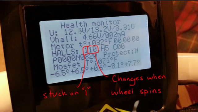
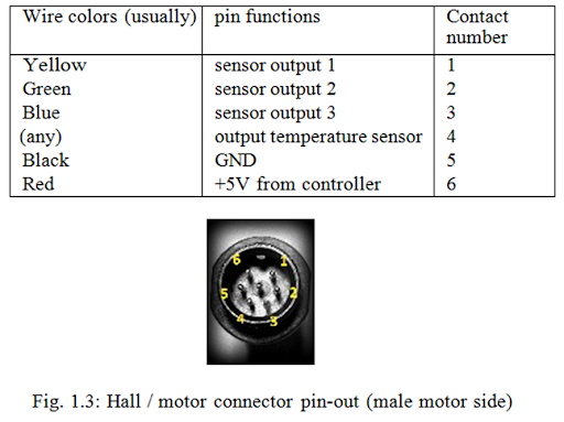
I narrowed down the problem to pin 2 on the hall sensor plug. I measured it with a multimeter, and it reads 0V. When nothing is connected to pin 2, the last two bits still switch when the wheel turns, but pin 2's bit (the first one) is still stuck on 1. Putting 0V or 5V to the pin does nothing, the display always shows "1".
Any ideas of how I can fix this? I feel something in the controller is fried, but I have no idea of how the halls work. They wouldn't just go to microcontroller pins, would they?
I'm in my 3rd year of EE school, and worked all summer on embedded systems.
Should I try for some kind of warranty, or should I try to fix it myself?")
I've spent a few hours each day all week trying to fix this. I've switched to the backup set of halls in the Cromotor, tried replacing the halls, and made sure they all work.
I made a simple Arduino sketch to test the halls.
Code:
//Hall Sensor Test.  Connect halls to digital pins 2, 3, and 4
void setup() {
  Serial.begin(9600);
  pinMode(2, INPUT_PULLUP);
  pinMode(3, INPUT_PULLUP);
  pinMode(4, INPUT_PULLUP);
}

  int twoOld = 0;
  int threeOld = 0;
  int fourOld = 0;

void loop() {
  int two = digitalRead(2); //read the three inputs
  int three = digitalRead(3);
  int four = digitalRead(4);

  if ( two!=twoOld || three!=threeOld || four!=fourOld) //if any of the halls have changed logic levels
{
  Serial.print(two);
  Serial.print("\t");
  Serial.print(three);
  Serial.print("\t");
  Serial.print(four);
  Serial.println();
}

  twoOld = two; //save state of halls for next cycle
  threeOld = three;
  fourOld = four;
}
They are definitely working, as this is the output when I spin the motor:
Code:
1	0	0
1	1	0
1	1	1
0	1	1
0	0	1
0	0	0
1	0	0
1	1	0
1	1	1
0	1	1
0	0	1
0	0	0
1	0	0
1	1	0
1	1	1
0	1	1
0	0	1
The Max-E screen shows the !halls! error. On the diagnostics screen, the second two bits of the hall status switch 0 to 1 when I turn the wheel, but the first bit is stuck on 1. Hall sensor voltage is good; powering the halls from a separate 5V source doesn't help. The sequence switches from H5 to H6, but H1-H4 never show.
I narrowed down the problem to pin 2 on the hall sensor plug. I measured it with a multimeter, and it reads 0V. When nothing is connected to pin 2, the last two bits still switch when the wheel turns, but pin 2's bit (the first one) is still stuck on 1. Putting 0V or 5V to the pin does nothing, the display always shows "1".
Any ideas of how I can fix this? I feel something in the controller is fried, but I have no idea of how the halls work. They wouldn't just go to microcontroller pins, would they?
I'm in my 3rd year of EE school, and worked all summer on embedded systems.
Should I try for some kind of warranty, or should I try to fix it myself?
By the way you can try the warranty route but the only way you'll get hold of them is by calling them on the second number on the invoice, as emailing them is useless. Depending on how good you are with soldering microelectronics you should be able to fix it. I can point you in the directin of the Russian forum if you like, some of them speak English but I find if I post with google translate and English you get a reply in either English or Russian, but if your using chrome you just right click to translate to English. They really know their stuff, I think they could possibly have some adaptto employees on there as they know exactly which components to check.
Just had a thought, in advanced settings you haven't changed the motor control from sine to another option have you, the only reason I ask is because one of the options is sensor less, the other option is to turn the third phase off, so not sure if that also turns the third hall off too. Also have you tried doing a system reset ?.
crea2k said:Looks like the 5v supply circuit for my halls is dead and that's why it wasn't working. I took a 5v feed from the usb port of the display unit and soldered it to the halls 5v input only, then took a ground from the display unit and soldered it to the motor to controller ground wire, just to make sure they are using a common ground and it now works fine, so for now il leave this bodge in place until I can take the controller apart to look at the power supply circuit for the halls, could be interesting to reverse engineer the schematics for it though to try and work it out, but at least I know what the problem is now. The strange thing is that the display unit says that the halls voltage is 4.85 volts, and that is even when its putting out 0.70 at the halls connector, so it must be measuring it upstream of the fault. At a guess its a coil or some kind of current limiting component that's died, but at least I know its not the motor or actual halls. If I cant work out the problem il have to send it back to Russia to be fixed, but im trying my hardest not too as they are a ROYAL pain in the arse to get hold of, they havnt answered my support email from about 2 weeks ago yet, so probably have to call them.
Not exactly the same, but I found out yesterday the reason my throttle went dead is that the standard 4pin connector from the display for the throttle harness broke, presumably from bouncing around the inside of my handlebars. The 5v source from the pads on the display was fine.
EDIT: Clearly I'm late to your fixing party! My phone didn't load the latest page when I checked. Congrats! Hope I never have to mess with the board.
Also got stopped by a cop for the first time ever after going 50mph over a short bridge with no shoulder on the interstate... he was nice, curious, thought that since I was in a roadway I needed mirrors and turn signals as well as my lights... I referred him to the appropriate rcw and he then said it's fine. I told him outright when he asked i understand I exceeded legal speed, but this was during heavy traffic and I felt that it was the safest way to proceed on the interstate without a shoulder. He said he'll "be in touch" and "send some information in the mail". We'll see if it's a ticket. All in all I'd do it again, but I definitely think mirrors and signals should work their way into my future for the fuzz.
xenodius said:Not exactly the same, but I found out yesterday the reason my throttle went dead is that the standard 4pin connector from the display for the throttle harness broke, presumably from bouncing around the inside of my handlebars. The 5v source from the pads on the display was fine.
I also had a problem with this connector. The GND wire was dead outright when i got the controller. After i cut off the rubber insulation i noticed a bad solder joint. I guess these connectors are bought in addition and not made by adaptto self. The strange thing with a broken GND wire: the throttle does work but the range shown in limit menu is a bit confusing. I can't believe i was riding the first days without GND connection. I noticed the failure not before i installed the variable e-brake (throttle and brake both interact).
Metallover
10 kW
I've tried a system reset, to no avail. I can get the bike to run on sensorless, but it is pretty lame. And unsettling when the motor losing sync. Switching to or from block control method does nothing to my halls.
I just found something else. Plot twist! The halls I have set up to pin 2 get killed when hooked up to pin 2! Hall killer! I saw them all work at the start; now 4 of my 6 halls are dead. Of the 4 dead halls, 3 are stuck on 0V, one is stuck on 3V.
I get 0V from battery ground to the phases, as well as 0V from hall ground to phases.
And my throttle has been cutting out since day 1. I better check my ground like you guys have been saying.
I think I'll try posting on the russian forum about my hall problem.
madin88 said:xenodius said:Not exactly the same, but I found out yesterday the reason my throttle went dead is that the standard 4pin connector from the display for the throttle harness broke, presumably from bouncing around the inside of my handlebars. The 5v source from the pads on the display was fine.
I also had a problem with this connector. The GND wire was dead outright when i got the controller. After i cut off the rubber insulation i noticed a bad solder joint. I guess these connectors are bought in addition and not made by adaptto self. The strange thing with a broken GND wire: the throttle does work but the range shown in limit menu is a bit confusing. I can't believe i was riding the first days without GND connection. I noticed the failure not before i installed the variable e-brake (throttle and brake both interact).
I noticed that there doesn't seem to be a lot of solder on the pads / wires inside the display unit for the throttle connector and power for the display etc, so i'm not surprised some of your have had them come loose.
Similar threads
- Replies
- 3
- Views
- 996
- Replies
- 85
- Views
- 6,264
- Replies
- 5
- Views
- 1,612