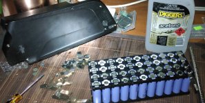
yet another solderless DIY battery pack via NIB's

wiredsim said:
So I received the nickel strips, I'm pleased with these so far- I may try using these with the foam pressure system as well. I ordered 8x1.5mm and 10x2mm N50s, I will be gluing these right to the strips if testing works out.

I think the N50s are a good investment here when price is reasonable. The higher price partly delivers more magnetism, and partly enables flatter geometry - more robust vs lateral forces. Will be interesting to see which resistances you achieve with them.

Does the newton force (~1/resistance) go linear with NIB N-number, or is there a sqrt(N) or N² law or so ?

Glueing: I also consider this for a final task. Though I did not notice any NIB movements after unpacking my battery several times out of the foam stuff used.
One danger of a glued contact unit perhaps: To unlink/uplift such contact unit in case of maintenance etc one needs to use 2 pliers or so and rather strong force while all is rather tight together. Now when loosing grip during that action, the contact unit with magnets all fixed could fall down and stick crossways to the cell contacts and create a very very fierce and ugly short cut situation because of the relentless magnet force. (Normal short cuts usually just produce a short plasma blow, some edge melts away and that it was.) So one should make good isolations of all nearby contacts during such maintenance situation.
Lifting individual 8mm magnets (hardly can bridge anything) and then lifting the force free link assembly is rather simple/safe.
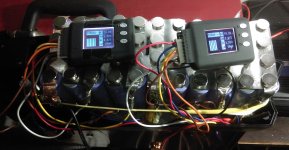
wiredsim said:
I have 2x holders, which are decent but I do get some warping which seems to straighten out once the batteries are in, but I'm thinking about moving to 3x or the 2x2 cases. These are all much cheaper on Alibaba/Aliexpress BTW.

Pictures will follow once the batteries come in.

With shipping costs I didn't find a cheaper source than Fasttech (shipping incl in prices) on the rush for low order quantities. If you got a good source, would be interesting.
 
radad said:
Every things been going great until a recent ride showed a huge voltage drop. I disassembled the pack and tested every cell. In the last parallel positive row, the corner cell was bad, measuring .4v I'm hoping it was a factory defect. I tested all batteries as shipped @3.63v then mass group balanced them before assembly. They only had about a dozen charge cycles. Hard to believe that one cell went bad so quickly and caused an additional sag of +2v.

0.4v only on 1 cell: so didn't the low voltage cell draw down the other 5 parallel cells as well? the 0.4 won't relax to higher voltage by itself? Perhaps the other 5 cells relaxed again to some >2.7v by itself, but the voltage of those cells stayed signifcantly lower than the other 13x6 cells?
Do you use a BMS / single cell UV protection? Or did you check for parallel balanced behavior of all cell groups near end of discharge some times, or at least once - in combination with controller sum under-voltage protection? Thus, could a significant under-voltage by over-discharge on that cell group have contributed to the death?

Crucial Question: Could the cell death be a effect of the NIB method as it?

Some probability may be there: upon a very bad contact (50mOhm .. 1Ohm) huge local heat could be produced on the plus cell terminal, affect the cell head / sealing, exponential self-speedup of self-discharge by oxygen traces ... death. Or: a high-z contact >1Ohm even, which results in over discharge of other cells in the group. So reliable good contacts are essential.
But corner cells are typically exposed to mechanical stress max by far. Any striking mechanical marks on the cell in question? The last plus terminal magnet bar yet may also rattle exceptionally depending on the plus battery contact cable geometry ... thus unreliable magnet contact by special mechanical cause.

The fact of a corner cell in question makes it unlikely (7%) that a simple over-discharge issue is randomly the original cause, and also it's unlikely that the cell was bad from production.
Without further info I'd guess 50% for mechanical damage of the corner cell directly, 40% for bad magnet contact issue (facilitated by uncaught plus cable mechanical forces or corner forces/bendings), 7% for unbalance/over-discharge due to cell cap variance as _primary_ cause, <3% for a bad cell from production.

PS: Its not officially safe to re-charge a deep discharged cell. But many do it and have luck :wink:
Lacking Li during deep discharge, internal anode contacting copper was discharged, it can deposit any time in future in a critical way and create a ugly "internal shortcut" . The probability for increased self-discharge is high also.
 
TheBeastie said:
I got my second order of fasttech cells successfully.
I only got enough for a 24v pack atm so I am not in a hurry to start building my nib pack.
I did out of wonder try to spot weld a nickle strip to a nib using a dodgey spot welder setup of a 233farad 12v ultracap (normally used for kick starting ICE motors) with nails as welder electrodes.
Well I can say for this dodgey experiment that the nib most certainly didn't like the heat from the spot weld attack lost most of its magnetism instantly.

After the soldering I also tried the spot welding on some magnets. Here some remains:
NIB_welding_S.JPG
The first shot at standard strength, which I typically use for welding nickel strips to cells, also immediately mostly demagnetized the NIBs. Worse: the mechanical connection was ridiculous. Broke after some slight force applied.

Then tried various other pulse strengths - and cooling: putting the magnet directly flat on a cool metal plate with thin layer of water on it in addition during welding. The cooling and dosed pulses helped to prevent crossing the demagnetization temperature. But never, with no kind of strong or weak pulses - caring about magnetism or not - did I manage to get anything like a good mechanical joint on these 8x1mm magnets, which have a very thin nickel coating (-> welding holes on the photo). With 8x2mm NIBs it might be little better when they have thicker coatings, but I hardly believe that one can get anything robust enough by welding to such standard magnets.

The magnetism over the thin 0.15mm strips yet is so undamped strong, the nickel surfaces rather the same, the lateral cohesion of all rather good (even without glue), the connection from cell to strip is most direct. So I don't feel the need of anything else, and didn't seek further in that direction.
 
you guys need to consider the toxic vapors released when spot welding too. not sure about neodymium oxide risk but nickel pentoxide is very hazardous. beryllium oxide is hazardous too.
 
I don't see the point in spot welding the magnets. If you can spot weld then eliminate the magnets. I think to me the point of this is to avoid having to weld and having a pack design that is easy to service and uses readily available parts.

My cost breakdown per cell right now is .11c for magnets, .26c per cell battery bracket and .18c per cell for the nickel sheet. for a total of 55 cents per cell additional cost. For the nickel sheeting I have, the cost increases if the pack is setup as anything other then 4p or 8p. If I move to 3P brackets or buy in higher quantity I can actually drop that cost pretty easily, I was surprised that ended up being the highest cost. So for a 10s4p pack the cost would be $22 (80 magnets, 10 nickel sheets and 40 2p brackets). Not including case or wiring of course.

You are right on the Fasttech price being good for smaller quantities, that is about what I paid for 2p brackets. You can get 1000ct quantities of the 3p for 7 cents on Alibaba however which would represent a big total pack price drop.
 
wiredsim said:
I don't see the point in spot welding the magnets. If you can spot weld then eliminate the magnets. I think to me the point of this is to avoid having to weld and having a pack design that is easy to service and uses readily available parts.

well, the second part of the "and", easy service & reordering, is interesting for people who can do spot welding too :)

wiredsim said:
My cost breakdown per cell right now is .11c for magnets, .26c per cell battery bracket and .18c per cell for the nickel sheet. for a total of 55 cents per cell additional cost. For the nickel sheeting I have, the cost increases if the pack is setup as anything other then 4p or 8p. If I move to 3P brackets or buy in higher quantity I can actually drop that cost pretty easily, I was surprised that ended up being the highest cost. So for a 10s4p pack the cost would be $22 (80 magnets, 10 nickel sheets and 40 2p brackets). Not including case or wiring of course.

so when thinking about the re-usability of all, the extra part costs (just the magnets essentially) become almost negligible.

Interesting will be how good and reliable those 0.2mm 2-dimensional shaped nickel pieces obviously will flex to the contact areas under the magnet force. I hope the situation is not too stiff. Perhaps some embossment work will be necessary.
 
well, the second part of the "and", easy service & reordering, is interesting for people who can do spot welding too :)

I understand! But my general rule is we should avoid placing the magnets in the path of current. Once you've tried using an adhesive, like super glue, you won't worry about spot welding anymore!

Interesting will be how good and reliable those 0.2mm 2-dimensional shaped nickel pieces obviously will flex to the contact areas under the magnet force. I hope the situation is not too stiff. Perhaps some embossment work will be necessary.

Yes I am very interested in that as well, I agree with the embossing. My biggest problem in that regards is the brackets warp and as a result will "pull" the nickel away from one cell versus another. I may combat this with some glue work on the brackets and clamping force and clamping of the whole pack once assembled. I'm waiting on the magnets, I mis-typed on my previous message.

Also looking at mounting / box options. Initially I'll probably use scrap wood but would like to use PVC ultimately. I had the crazy idea while at the hardware store of using 4" PVC pipe and heating it and warping it into a rectangle with some wood forms I would make. I may play with this in a few weeks if $$ allows.
 
wiredsim said:
I had the crazy idea while at the hardware store of using 4" PVC pipe and heating it and warping it into a rectangle with some wood forms I would make. I may play with this in a few weeks if $$ allows.
Look for PVC air ducts, they are square already, have seen them at least in 10x10cm and 10x5cm sizes, with plug ends and all you need. They are usually in extractor bell corners in the hardware stores.
 
x-speed said:
radad said:
Every things been going great until a recent ride showed a huge voltage drop. I disassembled the pack and tested every cell. In the last parallel positive row, the corner cell was bad, measuring .4v I'm hoping it was a factory defect. I tested all batteries as shipped @3.63v then mass group balanced them before assembly. They only had about a dozen charge cycles. Hard to believe that one cell went bad so quickly and caused an additional sag of +2v.


Crucial Question: Could the cell death be a effect of the NIB method as it?

Nikola Tesla is my hero. Unfortunately i'm like the dumbass under educated Edison just experimenting over and over. But I'm doing the best with what little theory I do understand.
I'm glad people are noticing this thread. I've learned a ton since starting this project. I have more questions now then in the beginning. One of which I never paid much attention to was magnet orientation. I figured clamping force is #1 so I always placed a N & S right on the cell terminals so as not to repel each other through the cell but to attract. I tried several different configurations like:
negatives all south, positives all north
pos south, neg north
all north on top of pack, south bottom
random
alternating patterns
all one pole on same busbar
I wonder what difference's it really makes, if any other than clamping force?

I finally turning my attention to the box again. My box old box was 1/4" poplar, hard to beat for rigidity , price and lightness. My version 4 box is PVC panel with AL angle. Its a little heavier and not as rigid. I looked every where for ip66 spec enclosure like 140 x 280 x 80mm no luck. I need a better idea for a good enclosure. I'm thinking ABS.

Elon Musk your my new hero! If your reading this please send me a 3d printer that prints in ABS and will input from a STL file
 
radad said:
One of which I never paid much attention to was magnet orientation. I figured clamping force is #1 so I always placed a N & S right on the cell terminals so as not to repel each other through the cell but to attract. I tried several different configurations like:
negatives all south, positives all north
pos south, neg north
all north on top of pack, south bottom
random
alternating patterns
all one pole on same busbar
I wonder what difference's it really makes, if any other than clamping force?

One can rather easy get a feeling for the forces by handling NIBs with a pincette or so. Magnets more than a few millimeters away from each other do practically not influence each others clamp force (immediately near surface) more than sub-%. Let alone the 6 cm's between cell plus and minus (despite the ferromagnetic cell material between).
Uncaught or strong residual lead wire forces yet are particularly evil with the magnet and elastic pressure methods - can cancel the magnet or elastic clamp forces - they are invalid with welding/soldering as well. The wires are best fixed to the cell holders - or to the box when there is stiff mechanical contact between holders and box; plus ensure for low residual forces in the fixed state.
And similarly evil are stiff situations with thick and/or 2D strips (contact leveraging effects) - can also cancel mag clamp forces.

When your dead corner cell at battery+ had no mechanical damage visible, such forces are perhaps most suspicious (together with contact preparation issues perhaps).

My concern about magnet direction of the (cylindrical) NIBs was/is only regarding impact on sensitive outer objects like cards, compasses etc. There, sum magnet field strengths much smaller than on the surface of the NIBs are already crucial. Direction alteration effectively cancels the magnetic fields on mid/far range here. If all NIBs of a complete pack made with NIB method have same mag direction, there is a rather strong mid range effect on outer objects - see the 100pieces stack experiment above.
 
wiredsim said:
Also looking at mounting / box options. Initially I'll probably use scrap wood but would like to use PVC ultimately. I had the crazy idea while at the hardware store of using 4" PVC pipe and heating it and warping it into a rectangle with some wood forms I would make. I may play with this in a few weeks if $$ allows.
Whatever box type, I think very important - more important than with welding methods - is that the box mechanics stays far away from directly jolting on the magnets & strips (& from plus terminals - even when welding/soldering). For elastic compression methods the issue would be even more crucial: The outer box peak forces must be rather decoupled from the whole (inner) compression mechanics too.

Thus: Either the holding forces from the box (with strong peaks) must be completely redirected to the cell holders alone (in all directions!), or/and there must be a good soft damping material thick enough to decouple and spread the forces effectively.
Generally I prefer to no not have a rather direct hard connection from the bicycle frame (or from potential stroke sources) to the cell holders/cans without suspension&damping means.
 
Got all my cells.
Doing a 4PS11 pack, basic layout in the pic so far.

I am doing some of the recommended steps such as sanding the contacts and cleaning them, you should be able to see that on the picture.
 

Attachments

  • IMAG0166551.jpg
    IMAG0166551.jpg
    310.4 KB · Views: 4,282
cwah said:
Any link to the magnet and other parts to buy? They'll probably end up expensivd
I recently bought some more magnets as I decided to go with my copper square style like radads which ends up being 4nibs per cell.
http://www.ebay.com.au/itm/281265208337?ssPageName=STRK:MEWNX:IT&_trksid=p3984.m1439.l2649
I really like 3mm by 12mm For negative side as suggested by radad.
I got some 2mm but it feels as if you get double magnitude magnetic force if you go even 1mm thicker, I don't know if we got any magnetologist mathematicians in our group but I would say magnetic strength increases exponentially compared to linear when you increase nib thickness/surface area.

I also ordered some nickle foil so I can have a whole square cut to cover joining p and s for each set of cells, I just felt thin Nicke strips traditionally used in spot welding felt too prone to letting bits fall off compared to having large squares iven if there were quite secured, visually you can count everything is accounted for when having larger single pieces.
http://www.ebay.com.au/itm/181440449126?ssPageName=STRK:MEWNX:IT&_trksid=p3984.m1439.l2649

As for price of the complete build well my argument is you can't put a price on a easily rebuildable battery pack. I feel a lot better about my pack compared to Hk lipos days where one bad cell turns into a real pain in the ass and I always have had a fear of ebikes haters stab attacks against my locked up bike, only takes one malice individual to quickly stab into a lipo pack and bbq my bike.
One idea for cell holders is wouldn't it be great if you could have one purposely shaped nib to hold 4cells together from in the Middle?
 
Here is the previously mentioned experiment of the 1/2 deox'ed copper coin, where 1/4 has been covered:
View attachment 2

Thin crisp oxide on the non-covered quarter after 2 weeks at room temperature:
copper 4th covered 2w S.jpg


The other quarter uncovered after 2 weeks:
copper 4th uncovered 2w S.jpg
=> conserved. no oxide layer there
 
TheBeastie said:
I got some 2mm but it feels as if you get double magnitude magnetic force if you go even 1mm thicker, I don't know if we got any magnetologist mathematicians in our group but I would say magnetic strength increases exponentially compared to linear when you increase nib thickness/surface area.

Here I measured the clamp force of 1 .. 3 NiB's N38 8x1mm to thick steel and to a SanyoUR18650FM cell can minus pole, also with contacting Ni strip sandwiched; done by using a scale, glueing the object to sufficient weight and then pulling upwards ..; compared to theoretical forces:

NIB-clamp-force.PNG

green circle: NiB measured has almost the theoretical force. (Its difficult to not have a small tilt at the moment of rip.)

Quote: "Yes, two or more magnets stacked together will behave exactly like a single magnet of the combined size."
Comment: At least as far as a rip doesn't take place between the magnets: red cicle.

x-speed said:
Does the newton force (~1/resistance) go linear with NIB N-number, or is there a sqrt(N) or N² law or so ?

Using a magnet calculator: Clamp force increases linear with N-number (N35 .. N52) :

NIB-force-vs-N.PNG

And force increases somewhat less than linear with NIB area, but more than linear with diameter: force ~ NIB_diameter ^ 1.33 .
(area ~ diameter ^ 2)

Surprising: When a NIB is put between 2 (thick) steel plates, clamp forces are a lot higher as when steel is only on one side; and there is saturation (early) :
NIB steel sandwich.PNG
The measured curve uses rather thin steel plates: still a sandwich effect, but with reduced saturation force.
(Note for comparison: the lower curve "theo. ThickSteel-M-Plastic" is the same as the "theo" curve in the 1st pic)
 
Anyway I just wanted to update everyone my nib pack.
Today I rebuilt my nib pack using the nickel foil as listed in my last post and removed all the copper sheets.
The consistent voltage performance is now heaps better then before. I barely gave my pack a perfectly even charge but I went for a small bike ride and all cells stayed very even in voltage according to cell-log. Before when I had the thicker copper inter-connects they were all over the place, clearly some cells weren't getting good connection.
This large improvement in level/consistent voltage I believe is due to having significantly thinner nickle sheet interconnections instead of the thicker copper sheet I was using. These thinner nickle connects can conform to any "unevenness" a lot better.
Ideally if I could create my nib pack so the cells are perfectly aligned then I guess it wouldn't matter so much but I have found trying to get my cells perfectly aligned very difficult.
 

Attachments

  • IMAG018122.jpg
    IMAG018122.jpg
    316.6 KB · Views: 3,882
TheBeastie said:
Today I rebuilt my nib pack using the nickel foil as listed in my last post and removed all the copper sheets.
The voltage performance is now heaps better then before. I barely gave my pack a perfectly even charge but I went for a small bike ride and all cells stayed very even in voltage according to cell-log. Before when I had the thicker copper inter-connects they were all over the place, clearly some cells weren't getting good connection.

Interesting status.
Is the voltage alignment (relative change over time) also measured during significant load?
Zero current quiescent balancer readings alone would hardly depend much on the quality of magnet contact resistance. Just if some cell would be rather completely disconnected... or on the very long run, when high-R caused local temperature increases would age cells quicker. Disbalance/drift at zero current readings mostly depends just on cell capacity spread, cell quality / aging ...
To evaluate contact resistances and changes <3mOhm even from dynamic balancer wire logs (with load) remains rather rough and difficult unless lot of averaging & stats is done.
I wonder if you could read some contact millivolt dropings rather directly (between cell terminal and nearby foil/NIB) with a voltmeter at known (charge) current, to get some impression regarding the contact resistances, variance of it, and if it is reliable on mid/long term.

Wonder if the thin (0.05mm) Ni foil could be cut with a knife easily into such shapes as user wiredsim wanted to buy (thicker 0.2mm) for standard cell holders? The thickness could be enough electrically due to the vaster 2D, and be decently for the NIB required flexing. It would all stick within the holder knobs, avoid cross wires/solder and intermediate magnets, though less customizable p-number. Perhaps at rather good price. I'm considering another pack with standard holders.

You seem to go without any holders. How is the mechanical cohesion achieved? There seems to nothing at all between non-parallel cells, which might become dangerous when shocks, mini-movements, temperature etc rub/disrupt the cell envelopes.

The foil pieces seem to be kept apart from each other and be prevented from slipping/shortcutting only by that foam pieces so far. Perhaps some rigid kind of sticks, plastic, wood,.. between the cells could serve in such holderless approach. Or longer isolating mats/plates between non-parallel cells as it.
 
x-speed said:
TheBeastie said:
Today I rebuilt my nib pack using the nickel foil as listed in my last post and removed all the copper sheets.
The voltage performance is now heaps better then before. I barely gave my pack a perfectly even charge but I went for a small bike ride and all cells stayed very even in voltage according to cell-log. Before when I had the thicker copper inter-connects they were all over the place, clearly some cells weren't getting good connection.

Interesting status.
Is the voltage alignment (relative change over time) also measured during significant load?

I wonder if you could read some contact millivolt dropings rather directly (between cell terminal and nearby foil/NIB) with a voltmeter at known (charge) current, to get some impression regarding the contact resistances, variance of it, and if it is reliable on mid/long term.

Wonder if the thin (0.05mm) Ni foil could be cut with a knife easily into such shapes as user wiredsim wanted to buy (thicker 0.2mm) for standard cell holders? The thickness could be enough electrically due to the vaster 2D, and be decently for the NIB required flexing. It would all stick within the holder knobs, avoid cross wires/solder and intermediate magnets, though less customizable p-number. Perhaps at rather good price. I'm considering another pack with standard holders.

You seem to go without any holders. How is the mechanical cohesion achieved? There seems to nothing at all between non-parallel cells, which might become dangerous when shocks, mini-movements, temperature etc rub/disrupt the cell envelopes.

The foil pieces seem to be kept apart from each other and be prevented from slipping/shortcutting only by that foam pieces so far. Perhaps some rigid kind of sticks, plastic, wood,.. between the cells could serve in such holderless approach. Or longer isolating mats/plates between non-parallel cells as it.
Here is the cell-log-s8 data in a graph after I went for a 10km bike ride to starbucks and back. Data record at 0.5 second intervals.
logview2.png
Cell group "3" showed the largest voltage drops by far, its either a contact issue somewhere or a more degraded set of cell(s).
Cell group "5" showed the highest consistent set of voltages, I have a chart here just to show the maximum contrast.
logview3.png
I will do the millivolt voltage drop while current is moving through test one day but right now I can't be bothered, I suffer from a chronic laziness condition.

This bike ride totaled 9.9km according to the bike LCD display. Using a total of 2.68Ah according to the watt-meter.
IMAG01822222.jpg

The nickel foil I ordered was very easy to cut up with scissors for any preferred shape. Only downside to the particular order I got was a bit of corrosion on the very edge of the nickle foil roll, like it had been sitting in a bit of water for a while or something.
For a more elaborate design using a cutting board/knife should be straight forward. If your wondering about strength its still significantly thicker then home food aluminium foil..

Yes while you can see I used cell holders on the very first pic I dismantled it all and tried to build it will no cell holders.
The main reason was that the cell holders were helping create and uneven level between P groups which when built with thicker copper made the electrical connections worse.
So I used light daps of a hot glue gun to stick sets of cells in 2S-4P configuration groups together with the glue and the rest is held together with the nibs and nickel foil. I also added bits of cardboard paper and foam between the nickel sheets/nibs.
All up while I am happy with the electrical performance but its physically dodgey and not safe, I will have to rebuild it with cell holders again.
So now that I have more easily conforming nickel foil going back to cell holders shouldn't inhibit electrical performance, and I have graphed data to compare it with.

Also the cell holders in my first pic are too big for P4 configuration with the battery case I bought. I can use another set of cell holders that came with that case that are smaller and do fit in the case but they also caused more uneven-ness between cell groups.
All up I wont be buying such a battery case again for a 18650 nib pack while it looks cool its pretty hard to use with a nib pack design as its internally uneven and has height restrictions for the nibs.

Here is the bulk of the bike ride on video, last 8 minutes going to Starbucks and then most of my ride going home.
Its recorded in 1080p but once upload it is so far surprisingly grainy in quality compared to original, hopefully the google cloud will magically fix it up over time. edit... hhmm after checking "Monetize with Ads" in youtube cp the video instantly started coming up sharper..

http://youtu.be/IEquEK_amTY
 

Attachments

  • cell-log8s.csv
    428.8 KB · Views: 131
TheBeastie said:
Here is the cell-log-s8 data in a graph after I went for a 10km bike ride to starbucks and back. Data record at 0.5 second intervals.
logview2.png
Cell group "3" showed the largest voltage drops by far, its either a contact issue somewhere or a more degraded set of cell(s).
Cell group "5" showed the highest consistent set of voltages, I have a chart here just to show the maximum contrast.

yes the group 3 with zero-current voltage running far off over discharge - continuously right from the the beginning - seems to have a completely disconnected cell, or dead cell.
The other groups show "just" a extremely varying voltage drop / resistance (factor 2), re-converging on zero-current. That could be due to the cells quality as it, but is unlikely for rather new cells. Even on a >5 year old Sanyo pack I don't get such high R-variance.
Thus the contact quality/treatment can likely be an issue. And perhaps leveraging effects of uncaught cable forces.
But without reference measurements directly with DMM on the connection/contact resistances, things cannot be really offseted from intra-cell issues.

I'd not do a lot of deeper discharge/charge cycling unless at least full disconnect issues feel mastered. When a disconnected cell suddenly reconnects with huge voltage offsets, strong currents can flow, strong charge currents on a single cell would be particularly threatening. R-effects in the magnitude of cell-Ri (as in my inital log diagram with untreated contact) can produce local heat.
Millivolt drop measuring and logging while doing some charger ON/OF is a safe controlled start.


A mobile log snippet from my pack with NIBs on #3/#4 (raw uncompensated):
android_smartBMS3_20km_snip_s.PNGandroid_smartBMS3_20km_snip.PNG
I have yet some unsymmetric positioning of the sense wire connections between some of the cell groups (including the NIB'ed ones), which accounts for most of the (constant) difference in voltage drops. Actual variance of the cell Ri as it can be computed by measuring and offsetting for the actual add-on restistances between sense wire connection points and cell pole ensembles/average (e.g. by doing millivolt drop measurement with DMM during a charge).
I have switched off balancing on the pack for evaluation since the beginning, with very small 2mV original disbalance pattern around 4V - which remained constant.
When compensating for these effects deltaU = I * R_addon (and relative overall cell Ri changes due to temperature/SoC, and averaging noise enough) I can see the remaining (NIB) contact resistance changes - total over all 4p of couse.

So far after 3 months and some 35 half-cycles average with that NIB pack I don't see any contact resistance change/instability issues by that log observation during rides.
I opened the pack 4 times, recently again after longer time, to also make the detailed millivolt drop measurements. The previous results were rather confirmed.
The resistances on the full treated (more critical) positive poles even became lower, continuing a little that strange self-improvement effect; all <2mOhm now with my rather modest magnetism. (The magnitude of mag force should be similar to that of that small pink circle - I forgot to mention - in the mag force diagram above on Sanyo cell, though its a different cell brand here).
Just 2 negative half treated contacts (no oxygen stop creme) became a little worse 2mOhm, they started from some 1.3mOhm, I watch it more, would do the full treatment when >2.5mOhm.
 
TheBeastie said:
Anyway I just wanted to update everyone my nib pack.
Today I rebuilt my nib pack using the nickel foil as listed in my last post and removed all the copper sheets.
The consistent voltage performance is now heaps better then before. I barely gave my pack a perfectly even charge but I went for a small bike ride and all cells stayed very even in voltage according to cell-log. Before when I had the thicker copper inter-connects they were all over the place, clearly some cells weren't getting good connection.
This large improvement in level/consistent voltage I believe is due to having significantly thinner nickle sheet interconnections instead of the thicker copper sheet I was using. These thinner nickle connects can conform to any "unevenness" a lot better.
Ideally if I could create my nib pack so the cells are perfectly aligned then I guess it wouldn't matter so much but I have found trying to get my cells perfectly aligned very difficult.

I'm not sure to see it clearly in the picture, but are you still using 2 magnet per connection (4 magnet per cell) so you clamp the nickel sheet between 2 magnet?

And I've seen these N50 magnet they should be enough?
http://www.ebay.co.uk/itm/Lots-100pcs-12mm-x-2mm-N50-Strong-Small-Disc-Round-Rare-Earth-Neodymium-Magnets-/371022461618?pt=LH_DefaultDomain_3&hash=item5662a97ab2

Plug these between nickel sheet in sandwich and it's good to go?
 
cwah said:
I'm not sure to see it clearly in the picture, but are you still using 2 magnet per connection (4 magnet per cell) so you clamp the nickel sheet between 2 magnet?

And I've seen these N50 magnet they should be enough?
http://www.ebay.co.uk/itm/Lots-100pcs-12mm-x-2mm-N50-Strong-Small-Disc-Round-Rare-Earth-Neodymium-Magnets-/371022461618?pt=LH_DefaultDomain_3&hash=item5662a97ab2

Plug these between nickel sheet in sandwich and it's good to go?
Yeah 2nibs per connection gives excellent hold and so far has done well to survive bumpy paths for me.
Biggest wrench in the works for me has been fitting the nib pack in my battery case, it's just too big with 3mm and is a squeeze with anything else. I actually have my last P with just nickle on the battery with the magnets on top (1 nib per connection) due to the slopping nature of my case it's the only thing that will fit, so far the performance of that setup seems to be fine.
 
So do you mean 1 magnet per connection (2 per cell) should be enough? I think it would save lots of weight and space.

Not sure if it's still as safe, but on yours it's ok isn't it?
 
cwah said:
So do you mean 1 magnet per connection (2 per cell) should be enough? I think it would save lots of weight and space.

Not sure if it's still as safe, but on yours it's ok isn't it?
I have been doing a bit of both lately on my pack, both methods seem feasible.
I also been testing with 4 layers of aluminium foil instead of nickle.

When drawing full amps Assist level 5 (around 35a) on the S12S controller it seems like some of the nib points get hot when I have them inside my plastic battery box. I normally ride with assist level 3 or 4 which seems to be a perfectly fine amp draw.

I think 12mm x 3mm nibs per connection seems quite usable but its most important to get the metal perfectly flat across the battery terminal, if the nickle has to bend over your cell holder plastic etc to reach the contact point for the nib then its going to be a bad connection.
Here is a pic where one of them is aluminium and rest are nickle.
View attachment 1
This one the hold side is aluminium while other is nickle.


Also for good value on nib purchases I found one seller I like, l-che27
I got my order in the mail after 9 days from China, other sellers it takes like a month for the same order to arrive.
Hes like 1 dollar more then the cheapest sellers but its worth it.
I measured my 50 nibs being 1.5mm and its 75mm total, other sellers they mesure out at like 70mm so there not perfect size, and there is normally at least one nib that is chipped.
Also l-che27 feel stronger so I believe they are genuine 50N strength magnets, some of the cheaper sellers seem to say 50n but are priced at 35n.

Also I got some bonus magnets with the order, some large chunky ones on both sides of the order.
So as far as I am concerned l-che27 is our guy for ordering nibs. http://www.ebay.com/usr/l-che27

015599795b21c55c871126c0beae8894232a4c50f6.jpg
 
Back
Top