Would you like a very small Lebowski brain board?

bowlofsalad said:
What I was thinking was making a mosfet box out of pre-made heat sinks, at least using a few heatsinks as a few of the walls, and then filling the box with mineral oil. There are pros and cons to everything, but I prefer the idea of filling the box with mineral oil to pumping water around. Using connectors stops fluid from wicking, you place the connector like you would a door to a room.

So this is clearly not for a bicycle and for a scooter or MC, right? If not, you should establish the power level, constant and burst you are after before attempting the impractical.

On an ebike, I can pump ~240A burst through 4 parallel MOSFETs pulling 175A battery, couldn't get the temp over 60C on the MOSFET case after several minutes of abuse.
 
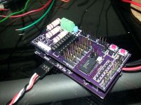
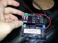
Boards have been received from OSH Park. I'm waiting on a few components, mostly headers and then I'll assemble up a unit for testing. If it works I'll build up the other 2 and sell them off to someone else who wants to experiment with this controller.
 
Just finished up the board builds of the small controller this weekend. I still need to fully test it, but so far I connected by serial interface and got into PWM test mode. Worked on the 2nd try, I had to swap my Rx/Tx serial lines.

Board layout could use some tweaking, but it's OK to use as long as I insulate 2 points. This was my first layout where I tried to match up 2 stacked boards using headers.

Pics
Lebowski-small1.jpg

Lebowski-small2.jpg
 
liveforphysics said:
Yes please. :)

One with a footprint for this amazing tiny $15 chip please. :)

http://ixapps.ixys.com/DataSheet/MTI145WX100GD.pdf

It would be like the power of a TO220 12-fet, but in a package perhaps 1/8th the size, and with the unbeatable control strategy Lebowski's brain uses.
Awesome find LFP! That also does away with the problem of matching the MOSFETs, as long as it could be cooled. Seems to me two of those for a x12 MOSFET controller would be very, very SCHWEET.
 
jkbrigman said:
Awesome find LFP! That also does away with the problem of matching the MOSFETs, as long as it could be cooled. Seems to me two of those for a x12 MOSFET controller would be very, very SCHWEET.


Upon further study, that package would not be the same as a 12 FET TO-220 based controller. RthJC of it is 0.85 C/W, that's bad. It also is limited by current carrying capacity of the legs.

As for matching, the distribution might be to be related to higher voltage devices. I haven't sampled enough devices to have supporting data. I've mainly worked with IRFB4110 (700ish) IRFB4115 (2000ish) and IRFP4568 (75). What I have found is that the IRFB4110's are statistically more likely to match up with regards to what Vgs the Miller Plateau is at. IRFB4115's have a wider distribution and are therefore less likely to current share equally when paralleled. Exact reason for this is unknown.
 
Njay said:
Good job zombiess, compact, nice form factor!

Thanks Njay. It was a lot harder to make this smaller than I thought it would be and it's still bigger than I want. It's finally starting to feel like I know what I'm doing when it comes to doing layout. When I look back at some of my early designs I cringe.
 
zombiess said:
Njay said:
Good job zombiess, compact, nice form factor!

Thanks Njay. It was a lot harder to make this smaller than I thought it would be and it's still bigger than I want. It's finally starting to feel like I know what I'm doing when it comes to doing layout. When I look back at some of my early designs I cringe.

It certainly looks good and small. I usually get a different feeling, not exactly pride, but more like accomplishment when I look through the versions of something and see a early version was barely functioning at best, or at worth a total waste of time/piece of garbage. We can only do our best with the skills and knowledge we have now. It's hard to be ashamed of ignorance when we are doing our best, and we are all so ignorant of so much. Failure is part of the road to success.

This might not be applicable to all situations, but I have used materials in new version of things take from the ruins of old projects. I have no idea if you could ever desolder SMD components and use them else where, but I suppose if it's possible maybe someday that'd be a thing to do.
 
I'm not ashamed of my previous work when I say I cringe. It's more of a "I can't believe it works as well as it does". It's mainly PCB layout I'm referring to as I have only really gained knowledge of good layout principals in the last 2 years. Previous to learning gate driver / power pass design I didn't have to worry about EM and noise much, slap a 100nF cap where appropriate and it's good. This was mostly micro controller and audio designs with a little bit of RF.

I learned at a very young age that learning electronics was as much about failing as it was succeeding, but I'm grateful that I never gave up. I started very young (age 8) and built many a non working project, smoked a bunch of bipolar transistors in push/pull setups driving transformers to make high voltage to shock people, etc.

Next version with be using a smaller brain chip from Lebowski, but first I should verify that this one actually works :)
 
zombiess said:
I'm not ashamed of my previous work when I say I cringe. It's more of a "I can't believe it works as well as it does". It's mainly PCB layout I'm referring to as I have only really gained knowledge of good layout principals in the last 2 years. Previous to learning gate driver / power pass design I didn't have to worry about EM and noise much, slap a 100nF cap where appropriate and it's good. This was mostly micro controller and audio designs with a little bit of RF.

I learned at a very young age that learning electronics was as much about failing as it was succeeding, but I'm grateful that I never gave up. I started very young (age 8) and built many a non working project, smoked a bunch of bipolar transistors in push/pull setups driving transformers to make high voltage to shock people, etc.

Next version with be using a smaller brain chip from Lebowski, but first I should verify that this one actually works :)

Has everything worked out?

How would you mount these boards to something? Maybe you didn't design these for something like that.
 
Watching this thread with great interest.
Will you also design the power stage boards that go with it?
Or is this everything down to the mosfet gate drivers and the rest is up to the end user?
Thanks!
Chris
 
Would you like me to send you a sevcon gen4 size6 that has an undamaged power stage, but was damaged by drilling into its brain-board with a big drill bit by mistake.
 
liveforphysics said:
Would you like me to send you a sevcon gen4 size6 that has an undamaged power stage, but was damaged by drilling into its brain-board with a big drill bit by mistake.

What mosfets does it have, Luke? any photos?
 
I am also interested in this SMD Lebowski brain FOC controller board. :mrgreen:
Is there an estimated date for a small batch?
 
heathyoung said:
One of these and a Mitsubishi PM300CLA060 would be killer :)

300A 600V IGBT 3 Phase module - integrated gate drive, short circuit protection, complete with desat detection. Bolts not solder for connectors... And a completely different SOAR curve to mosfets (you can use all its capability).

Very difficult to kill these little buggers too. You usually melt off a terminal first.
Less than 100 quid: http://www.ebay.co.uk/itm/301351885741 :D

Can someone point me in the right direction how to drive them from this board? Maybe I missed something - is there a downside?
+1 on an update - interested in 2 boards as well
 
marcexec said:
heathyoung said:
One of these and a Mitsubishi PM300CLA060 would be killer :)

300A 600V IGBT 3 Phase module - integrated gate drive, short circuit protection, complete with desat detection. Bolts not solder for connectors... And a completely different SOAR curve to mosfets (you can use all its capability).

Very difficult to kill these little buggers too. You usually melt off a terminal first.
Less than 100 quid: http://www.ebay.co.uk/itm/301351885741 :D

Can someone point me in the right direction how to drive them from this board? Maybe I missed something - is there a downside?
+1 on an update - interested in 2 boards as well

There is a circuit digaram on the datasheet, if you build that as is (including the DC-DC isolators) and connect the optocouplers to the dsp (you wont need the mosfet driver part)
you will also need some current sensors for each phase. tuning the software side - i have no idea at all,

this is pretty much what im planning on doing, i need a 400v 400A or thereabouts controller for my remy 250hvh.

If i had a choice of switching money no object i would get a SiC Automotive power module many advantages to silicon carbide.
http://www.powerguru.org/the-silicon-carbide-jfet-in-3-phase-power-supplies/
 
My plan is to take a break from some of the other work I have been doing the last few months and finally get this working with my 18 FET power stage. This small brain board has been competed for several months and I verified pwm, but have not run a motor yet.

If you are looking into building a controller, please understand it is not easy to design a good gate driver or power stage for controllers over a few kW. There is a lot of noise when you sling around hundreds of amps at 20khz.

The good news is my gate drivers are now going to be tested under real conditions so I'll know if they work correctly or not.
 
usertogo said:
I am hoping to run up to 154V LFP system,


I'm struggling to see what could motivate a person to choose such a no-mans-land voltage. Is part of your project criteria needless complexity and expense in BMS and controller? Have you ever seen a MOSFET that makes it a good choice for that voltage or were you planning to go IGBT and eat the Vf loss for higher system inefficiency?
 
Time for some action, it's been too long. I'm taking a break from another project I've been working on daily since late August which coincidentally is exactly the same time I stopped progressing on this controller. Sorry about that people who have been waiting for updates. I've been on a knowledge quest like nothing I've been on before for the other project. I've been studying control theory, physics, algebra, calculus, trigonometry and pretty much every nerdy totally awesome thing that relates to future plans I have. I need to have a solid foundation in the above because I've been doing a some theoretical work based on existing knowledge I had, but I need a deeper understanding.

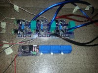
Anyhow, enough about that, here is a progress picture as of a few mins ago. Controller, Lebowski brain board with sensorless configuration and the 600A current sensors I'm planning to use. Not quite sure how the current sensors will be packaged yet, I might need to make them external since it's such a tight squeeze, but I got some ideas, but I may need to break out the big ass soldering iron which has some risks to rework my phase connections.

I've already come up with many improvements to make on the next version which will probably have 5-6 TO-247 MOSFETs in parallel to see how far I can push the limits, I have 600A current sensors so... :twisted:

I'm hoping to have this thing spinning a motor this weekend if the rest of the testing goes OK. I'm in progress of doing all the tedious wiring required. I'll be posting more updates as I go.

IMG_20141212_174805.jpg
 
liveforphysics said:
usertogo said:
I am hoping to run up to 154V LFP system,


I'm struggling to see what could motivate a person to choose such a no-mans-land voltage. Is part of your project criteria needless complexity and expense in BMS and controller? Have you ever seen a MOSFET that makes it a good choice for that voltage or were you planning to go IGBT and eat the Vf loss for higher system inefficiency?

I have to agree with Luke on this. That's an odd ball voltage, but if it's what you need then it's what you need. If it's flexible, you might want to consider going < 120V. If you must use IGBTs, then you should probably make it worth while and run +200V bus. If you go the high voltage route, you better darn well make sure you know what you are doing and the safety procedures required. Mistakes will not be forgiving. Because of that, I strongly suggest starting off starting small and working your way up as you learn. Gate driver/power stage design/layout looks easy to do in app notes and in papers. But it's incredibly hard. Gate drivers are a wolf in sheeps clothes.
 
Gate drive and trace layout is maybe 90% of what makes a controller.
 
Back
Top