Open source integrated EV Electronics system

Teslafly

10 mW
Joined
Jun 18, 2013
Messages
31
Location
Platteville or Wausau Wisconsin
Open source integrated EV Electronics system

NOTE: this post is just for discussion of goals, protocols, and what projects to base systems off of. It is not for active development.
Another post will be made for that purpose once the description, goals, and purpose are refined and solidified. (And because of that, don’t be afraid to let out your inner grammar demons run wild)

///_________________________________________________________________________________///

There seems to be a severe lack of open source ESCs, BMSs, and other EV Subsystems on the market. The ones that are have very little integration or seem to be extremely expensive and hard to set up.
This project aims to fix these problems by designing an open source vehicle electronics system, standardized communication protocol, and programming tools for all units to use.
(more explanation and definitions are needed here. What's your vision?)

There are a couple systems similar to this that exist already, but all seem to have stagnated or not have as comprehensive as an outlook with an extreme ease of use. (I could not find any commercial systems - If there are any community projects that I missed, please point them out.

One of the most important things to prevent this project from suffering the same fate will be developing at least one module (The display, BMS or motor controller) and getting it on the market at a competitive price as soon as possible. I am capable of building low quantities of PCBs and running an online marketplace, but am currently attending the University of Wisconsin Platteville for electrical engineering and may not be able to devote all the time needed. If this gets far enough to have working, sellable hardware, then we will need someone to take up this very important job.

14927597957

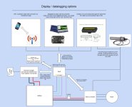
This image isn't showing properly. Can you guys help? attached to end of post instead.
Initial system block diagram (Any other good & free diagramming software out there? Gliffy sucks)


GOALS

Open source
All hardware and software must be open source. Hardware files will be hosted on a widely used, easily accessible site (suggestions?) so that it won't just disappear someday. Software will be hosted on github. (Any other suggestions are welcome though)

Ease of programming
This system should be relatively easy to program. All compilers should be commonly available for reflashing firmware, and IO should be able to be programmed a graphical programming site (Ladder logic?) without needing to reload the firmware. Ideally there will be no special adapters, and all programmable devices used should have a usb connector (and preferably usb on chip? No FTDI stuff if it can be helped ). This shouldn’t add much cost, if any, and makes the system much easier to use. It also makes it easy to connect something like a netbook and do work out on the field and on the go.

For the firmware compiler, there are several that the community know quite well, but only that I know well. Please suggest some and I’ll add them to the list.

As for the graphical programmer that will be used to program overall system behavior, either a graphical flow (dataflow) programmer or one of the ladder logic programmers that the community has developed could be used. (If a wireless/otg link was used, could the programs based on a webserver be edited on a smartphone/tablet??!)
There are several dataflow programming languages that could be used. The ones that I know of are listed below. Please point out others that may be a good / better fit.

There are a couple open source ladder logic programs that have been developed by the community and could possibly be developed further for use in this system.
They include;


Cost
The systems should be relatively cheap, but not quite as cheap as Chinese made parts. (but also much higher quality.) Maybe 50% over parts and assembly costs? I don’t know. I’m not an economist. Whoever builds them will need to figure that out. If they are good enough and still too expensive, someone will come along and make them more affordable. The important part is that they are readily available for builders to use and improve.


What needs to be done?

Pick a License
What open source license will this project use? This will be somewhat dependent on the licenses the “base” projects use, but could be changed with permission. Would a “viral” open source license be best? (if you use and improve some part of the code, you must publish the result) or a free for all “you can monopolize it, take it for what it is and not share, build a business advantage with your improvements, etc” approach work best?
I would really like to hear feedback on this one, especially from people who have actually read through various open source licenses and really understand them.

Pick base projects
let's not reinvent the wheel here.(bah, hubmotors :D ) There are plenty of fragmented open source projects for each of these modules and bits of software floating around the community.
Existing base projects need to be chosen for all of the modules (with the original author's permission of course) and integrated into the system.


Choose a data protocol and standardize communication methods between modules
What protocol should be used for communication between modules?
it should be...

  • - Isolated
    - high-ish speed
    - reliable (low error and not prone to electrical disturbances)
Can be either a single bus for all modules, or need a hub for branching out. The BMS could serve as this hub
Create several subsystems that can work together but also independently if needed. Any module can be connected to any other module/s and get useful data / connection if there is any data to be had.

Serial or CAN bus communication may be good candidates for this, any comments on this?


Develop the first module and setup a marketplace
Someone will have to build and sell these modules to make them commonly available. If this isn’t done, very little new people will come in and be able to contribute to the project. What remains to be seen is:

  • 1. Which module will be first? Which module can operate on it’s own the best and is most sorely needed in the community? A BMS, an open motor controller, or a better display? I believe the BMS is needed the most, especially for custom hobbyking packs.
    2. Who will make and sell it? Will someone that already has experience with this sort of thing step up to the plate? Or will someone new do it? Please express interest if you are up to the challenge.

These questions can wait a bit to be answered, but these problems need to be solved past a certain point in the project.
 

Attachments

  • EV control system resized.jpg
    EV control system resized.jpg
    198.1 KB · Views: 3,891
SUBSYSTEMS
All subsystems should be able to work together, but also independently if needed. (Either because there are no other compatible systems, or because the communication bus failed) All subsystems attempt to cover a wide range of uses, from escooters and ebikes, to full sized electric cars.

ESC
The motor controller should be capable of brushed and brushless operation software wise, but it’s main domain will be brushless. At least capable of driving a permanent magnet brushless motor, but the control algorithm for ac induction motors should also be added. I do not believe there are any hardware differences needed for permanent magnet vs induction based motors, but please correct me if I’m wrong. Sensored and sensorless control should be possible with all motors. If possible and not prohibitively expensive, it should also be able to monitor it’s own current consumption and
There should be 2-3 versions of the motor controller.
1. 12-60V at with 50-250 amps of mosfet ability with same gate driver.
2. 30?-150?V with 50-250 amps of mosfet ability with same gate driver.
3. A board with just the microcontroller, power supply, and other minor things. Gate drives, voltage dividers. And IGBTs / mosfets are off board. This allows for the building of a controller in the 200-800v range capable of several hundred(thousand?) amps.
Existing open source projects / threads that could act as a base for this include:
Any projects that we missed of you don’t think should be on the list? Please comment! (This goes for the rest as well.)


BMS
A digital BMS that also actively balances cells. (bleed resistors, etc) It would only work on lithium chemistries, but the voltages for balancing and such are adjustable (and can even be set lower to increase battery life)
One master unit with sub units daisychinable for more cells. Also provides low voltage power to all other systems, controls the contactor (if there is one, otherwise it’s just controller enable) and acts as a communication hub for everything else.
There could be two versions of the bms. One that uses a daisychainable chip that manages multiple cells (like the BQ76PL536A) and has a relatively low balance current this could be used for hobbyking packs and ebikes. And a single cell version that is daisychained across cells and has something like an attiny per cell. This could work for full sized vehicles (>50ah per cell) with balancing current in the range of 0.5-2 amps.
Resistors! What resistors? A cheap and easy way to make a resistor is just to put a squiggly trace of a certain length and width on the bottom/end of the board. This works well enough in the 3d printer world, and I think it could be used here. http://reprap.org/wiki/PCB_Heatbed

Existing open source projects that could act as a base for this include:


Display

The display should be capable of displaying, at the very least, speed, battery level, current, kwh, and system faults.
Datalogging, a real time computer connection, and actual control of the system should also be an end goal, but is not strictly necessary.

There are three ways that I believe this could be accomplished.
1. Modified cycleanalyst that pulls its data from a bus instead of individual sensors.
2. Smartphone and wireless bridge.
3. Single board computer (beaglebone black?) with (touch?)screen.

A modified cycleanalyst would be the cheapest option. I’m not sure if that project is open source or not, but if it is it would be quite simple to modify to be compatible with this system. This is also the cheapest option

A smartphone app could be developed on something like phonegap (fairly easy cross platform porting) that would communicate to the system over Bluetooth/wifi. This is relatively low cost for high functionality, but does not allow the user to use other apps for navigation or such while driving.

A single board computer running a screen, possibly a touchscreen, would be the most capable but expensive option. It would be able to coordinate programming, display complex values and menus, allow for quick reconfiguration on the fly and be able to perform high speed data logging. (All of which the phone / tablet can do and avoid the all the expense though) That, or this system could be cut out in favor of using the phone bridge with a cheap, permanently installed android tablet or such. (Possibly running usb otg)


Auxiliary IO module

All the other modules will have a certain amount of leftover io to connect to peripherals, but none of it will be high current outputs for running lights, solenoids, relays, and others with the exception of the contactor driver/s on the BMS. This module will allow logic flowthrough and control of other vehicle systems such as turn signals, headlights, the radio, ac and others. The hardware won't be too hard here, but easy programming of this module (and its integration with the rest of the system) will be somewhat difficult. Especially considering that there may be more than one of these modules needed. (Now that I think of it, I can come up with scenarios where more than one of all the other modules would be needed as well. This scenario will need to be accounted for eventually, but not at first.)
Not really any existing projects here. It hasn't been needed because the integration between systems was so low in the past.
 
This is all pretty interesting; I was actually planning on building a prototype bike running open-source "Endless-Sphere" electronics at some point (but I'm broke right now and will most likely continue to be broke for a few months or longer); the idea would be to use a Lebowski controller for the motor, a bulk charger of my own design (still working on that) combined with a Hecker/Fechter/Goodrum 24s hardware BMS, and then either a modified Cycle Analyst or a tweaked Arduino-based LCD rig similar to this thing Charles Guan did hooked up to current sensors on the battery wires (and phase wires). Making all of these things talk to each other directly is going to be entertaining; as far as I'm aware the BMS is intended to be mostly self-contained, and I think the Lebowski controller can talk over CAN or via analog; it might be necessary to use an Arduino (or maybe even a PSoC-style ARM dev board) to act as a centralized brain for the whole system if you want convenience and integration on par with an Adaptto setup.
 
I once had an idea for an integrated system to help make a "safe ebike" for the masses, but didn't get the help and input needed to really get it started.

If any of hte ideas are useful, what little I ended up specifying for it that still exists (had a lot of other notes and designs but lost in a fire) is here:

https://forums.adafruit.com/viewtopic.php?f=26&t=7346


At one time, an "ebike OS" thread was started here on ES:

http://www.endless-sphere.com/forums/viewtopic.php?f=3&t=15022
But it didn't go anywhere, either. :(
 
Hi,

not sure how useful this will be, but I built / developed and open sourced my electric range meter. Here is the sourceforge page:

http://sourceforge.net/projects/bangxietymeter/

It's not complete, but works.

I've not fully documented it, but would be happy to answer questions on it.

It uses a cheap display and all the hard work to use it is already there & It's arduino based.

hth

sp
 
Teslafly said:
Open source integrated EV Electronics system
There seems to be a severe lack of open source ESCs, BMSs, and other EV Subsystems on the market. The ones that are have very little integration or seem to be extremely expensive and hard to set up.
This project aims to fix these problems by designing an open source vehicle electronics system, standardized communication protocol, and programming tools for all units to use.
(more explanation and definitions are needed here. What's your vision?)
I think that part of the reason there's a lack of parts that are open source is that there are plenty of cheap, closed source (Chinese) products out there and the DIY EV market, especially for small EVs and eBikes, is very price sensitive. Open source does not necessarily equal cheaper or better, and when you're stringing together cheap lipo packs, paying extra for a high end BMS generally doesn't appeal. Not saying this shouldn't be done as I'm a big fan of open/community projects (the last 2 BMS links you posted are my designs), just that it will be slow going at first and probably not financially profitable. If that's not your goal, then good luck and I'll be happy to help.
 
Thanks for the links guys.
I am actually very aware of the things Charles has done. I've been following his blog for years now. (and have learned lots from it, especially about motors and gate drives)

As for dmwahl, I know that if this system isn't cheap / full of enough features that no one will want it. The Chinese market is full of low end (and some high end) products for repetitively cheap, but from what I've seen, especially with the BMS's that the low quality is no where near enough. (There's a reason that Chinese BMS systems have occasionally earned the nickname "battery killers".) I believe that a good first project would be the BMS system, and my goal is to make it cost less than $2 a cell on the user end (that's with markup..!! :shock: ) in manufacturing quantities over 100 units. I actually like your BMS design based on the BQ76PL536A very much. It consolidates some of the circuits, is daisychainable up to 400volts worth of cells, and still relatively simple. I was planning to make a couple prototype boards based on it, but in the process I found this chip, the ATA6870N-PLPW (http://www.mouser.com/Search/Produc...virtualkey55660000virtualkey556-ATA6870N-PLPW) It's a bit cheaper, especially in high quantities, and a bit simpler to use in terms of the data bus. If you want once I am finished putting together a pcb in kicad I could point you to the link so you could take a look at it, then once I fab a couple I could send you 1-5 for something like $10 a board (I'm a college student, I can't just afford to just give crap away for free!)
Also, I have a question, do you have any idea how much balance current is needed on a BMS? I was thinking about 1 watt of resistors per cell, but that's kind of a lot I think, but I really wouldn't know.
 
Teslafly said:
I actually like your BMS design based on the BQ76PL536A very much. It consolidates some of the circuits, is daisychainable up to 400volts worth of cells, and still relatively simple. I was planning to make a couple prototype boards based on it, but in the process I found this chip, the ATA6870N-PLPW (http://www.mouser.com/Search/Produc...virtualkey55660000virtualkey556-ATA6870N-PLPW) It's a bit cheaper, especially in high quantities, and a bit simpler to use in terms of the data bus. If you want once I am finished putting together a pcb in kicad I could point you to the link so you could take a look at it, then once I fab a couple I could send you 1-5 for something like $10 a board (I'm a college student, I can't just afford to just give crap away for free!)
Also, I have a question, do you have any idea how much balance current is needed on a BMS? I was thinking about 1 watt of resistors per cell, but that's kind of a lot I think, but I really wouldn't know.
I also looked at the ATA6870, but availability was 0 at that time. Looks like it has improved a little since then. That said, if you stick to the BQ76 chip I can supply you with code to start with that already has the communication basics worked out, which IMHO is well worth the cost difference. If you decide to go with the ATA6870 though I'd be happy to buy a few from you to play around with.

Regarding resistor value, there's a common misconception that you start shunting current only at the end of charge (ie 3.65V for LiFePO4) and that you need the shunt current to match or come close to the charge current. In reality, if you start the balance early, say 3.50-3.55V, then the shunt current requirement goes way down. You can fairly easily balance a large pack with only a small current. For a digital design I would recommend 1x 5ohm/5W or 1x 10ohm/2W resistor per cell. If that turns out to be too much heat then you can always lower the duty cycle. The BQ76PL536A that I'm using has a register setting that makes adjusting duty cycle very easy to do, I would guess that the Atmel chip has a similar function.
 
Teslafly said:
Open source integrated EV Electronics system... NOTE: this post is just for discussion of goals, protocols, and what projects to base systems off of....
Since you're early on, I suggest a collaborative relationship with Technocopia, aka Neuron Robotics. This group of WPI.edu graduates is composed of electrical engineers, coders, roboticists and others committed to open source protocols of general utility to everyone in the field. In my conversations with them, they have expressed interest in extending their protocol to LEV controllers as you suggest. They are managing code in Java at https://github.com/Technocopia. The repository is out-of-date because the talent is over-committed. PM me if interested.
 
I also looked at the ATA6870, but availability was 0 at that time. Looks like it has improved a little since then. That said, if you stick to the BQ76 chip I can supply you with code to start with that already has the communication basics worked out, which IMHO is well worth the cost difference. If you decide to go with the ATA6870 though I'd be happy to buy a few from you to play around with.

yeah, the availability is still 0 at mouser(an order should arrive in about 3 months), but digikey has a couple thousand in stock. I looked through the amtel ATA6870N datasheet as well as the datasheet for the BQ76 and compared the two. One thing I particularly like about the amtel chip is it's simplified communication bus. This would allow the interconnections between sub boards (one chip per board. simple and scalable) to be much simpler, as well as reducing the communication connector count from three to two. some other advantages are a lower standby current, a balanced ldo drain across all packs for powering the microcontroller, slightly simpler communication and of course, the amtel chip can be had for around half the cost of the BQ76 one. As of now, I am leaning heavily towards that one.

If I may ask, what exactly do you all have working in your code? data bus initialization, reading the cell voltages, and what else?

Also, I believe the best communication standard to make this system work would be the CAN protocol. The transceivers can be had for around $1, are highly robust, and can traverse quite long distances. As I am aware of no low power arduino compatible microcontrollers with an integrated controller area network module, (with the exception of the Teensy 3.1with it's MK20DX256, which I have, and the chip is decent at a cost of $7, but at 1ma in standby mode and 26ma running, it's not exactly low current) I am hesitant to choose a balancer based on available code. There is no guarantee that the code you have created will even be applicable to a microcontroller capable of running the system. Neverless, my specialty is more on the pcb/hardware side, not software (even though I have a good amount of expedience) If I have to start from scratch with the ATA6870N it will be a good opportunity to further my programming knowledge of communication / data protocols as I have not worked as in depth with them before, but as a freshman EE at UW Platteville, I will have plenty of resources to help teach me these things.

Also, I looked through your code more thoroughly, what do the parts about android do exactly? It looks like a usb otg thing? I am currently stuck with an apple product (but will be switching to android) and haven't really had a chance to do much with android and arduino.

As for the balancing, 2W at 10 ohms sounds like a good starting value. I did not find a pwm function in the ATA6870N datasheet, but 50% pwm by bit-banging it on/off once a second would probably be doable if needed. I will be putting one thermistor connected to one of the temp inputs on the pcb, and the other sensor will be broken out for attachment to the pack.


Since you're early on, I suggest a collaborative relationship with Technocopia, aka Neuron Robotics. This group of WPI.edu graduates is composed of electrical engineers, coders, roboticists and others committed to open source protocols of general utility to everyone in the field. In my conversations with them, they have expressed interest in extending their protocol to LEV controllers as you suggest. They are managing code in Java at https://github.com/Technocopia. The repository is out-of-date because the talent is over-committed. PM me if interested.

I may take you up on that. If I can get in with someone a bit more knowledgeable to define a data protocol (although using can as a starting point?) it will make things much easier on me if I am to go forward with the whole thing.
 
Actually, scratch what I said about the teensy 3.1 being a current hogging beast. I took a closer look at the datasheet (https://www.pjrc.com/teensy/K20P64M72SF1.pdf) and found a couple tables on pages 14 to 17 that give the current consumption throughout many modes of operation. specifically 30 uA when in low power stop mode, and between 2 and 6 uA in low leakage stop mode. That's good enough for a BMS system that won't kill your battery over the course of a couple of months. It's compatible with arduino (although I'm not sure if any of the low current functions are available in that yet), and will be easy ofr people to use. if we can't use arduino, then the compiler is known to be easily available. continuing on current draw, we also have about 20ma to work with from either of the BMS chips for actually running the processor. According to page 17, if I run the processor at 12.5 mhz (plenty fast) we can get the current draw under 10ma when running as well. This means the mk20dx256 used in the teensy 3.1 can be the processor for this application. (Not to mention that it has usb-otg, so the android connection will also be possible)
 
Teslafly said:
I looked through the amtel ATA6870N datasheet as well as the datasheet for the BQ76 and compared the two. One thing I particularly like about the amtel chip is it's simplified communication bus. This would allow the interconnections between sub boards (one chip per board. simple and scalable) to be much simpler, as well as reducing the communication connector count from three to two. some other advantages are a lower standby current, a balanced ldo drain across all packs for powering the microcontroller, slightly simpler communication and of course, the amtel chip can be had for around half the cost of the BQ76 one. As of now, I am leaning heavily towards that one.
The chip to chip communication is dead simple for the BQ76, it's a current mode interface so just connect the dots in your schematic and go. I think the Atmel uses the same method of signaling between chips. I would advise against having multiple boards though, all of these battery management ICs are really intended to share a PCB.

The problem with the Arduino boards themselves in regard to power consumption is not the mcu itself, which is just a standard ATmega, it's the voltage regulators that are not that efficient. In my designs I just use a straight ATmega328P (or other MCU), and more efficient power supplies. It's "Arduino compatible", so you can use the Arduino IDE, which is the real draw of the Arduino platform. Total current draw of under 100uA is easily achieved, which for our purposes is negligible.

In general, I don't consider Arduino, Teensy, or any of the other microcontroller platforms as anything but a dev tool. The Arduino Pro Mini is a possible exception since you can bypass its internal regulator and supply 5 or 3.3V directly, but for the most part they are all designed for low cost tinkering without needing to worry about the low level coding behind the scenes. Some of the built in commands (such as the "DigitalWrite" command, are really just wrappers for flipping a bit and horribly inefficient. I believe that the DigitalWrite command takes something like 12 clock cycles to complete, vs 1 for just flipping a bit on or off directly. Fine for playing around, but if your code takes 10x the time to execute, then your microcontroller needs to be awake for 10x the time, and your power consumption goes up ~10x.

Teslafly said:
If I may ask, what exactly do you all have working in your code? data bus initialization, reading the cell voltages, and what else?

Also, I believe the best communication standard to make this system work would be the CAN protocol. The transceivers can be had for around $1, are highly robust, and can traverse quite long distances. As I am aware of no low power arduino compatible microcontrollers with an integrated controller area network module, (with the exception of the Teensy 3.1with it's MK20DX256, which I have, and the chip is decent at a cost of $7, but at 1ma in standby mode and 26ma running, it's not exactly low current) I am hesitant to choose a balancer based on available code. There is no guarantee that the code you have created will even be applicable to a microcontroller capable of running the system. Neverless, my specialty is more on the pcb/hardware side, not software (even though I have a good amount of expedience) If I have to start from scratch with the ATA6870N it will be a good opportunity to further my programming knowledge of communication / data protocols as I have not worked as in depth with them before, but as a freshman EE at UW Platteville, I will have plenty of resources to help teach me these things.

Also, I looked through your code more thoroughly, what do the parts about android do exactly? It looks like a usb otg thing? I am currently stuck with an apple product (but will be switching to android) and haven't really had a chance to do much with android and arduino.
I have the basic communication, error checking, voltage measurements, and balancing working. The toughest part was figuring out the communications, once that was done it's just a matter of moving data in and out of the various registers. The code that Matt posted is different from what I wrote, I used a few bits and pieces of his code but it was easier just to rewrite since his application was significantly different. Mine is not posted anywhere since it's more of a test program than a deployable firmware. Once it's done and I'm happy with it, it will be posted online. I'm happy to share it with people on an individual basis, but I don't want it public until it's more refined.

Teslafly said:
As for the balancing, 2W at 10 ohms sounds like a good starting value. I did not find a pwm function in the ATA6870N datasheet, but 50% pwm by bit-banging it on/off once a second would probably be doable if needed. I will be putting one thermistor connected to one of the temp inputs on the pcb, and the other sensor will be broken out for attachment to the pack.
The register I use is actually a balance timeout (CB_TIME). You set the timeout to anything between 1 second and 60 minutes, and then unless the chip receives a new command to turn on the balance resistor, it will shut it off after the timeout. I measure voltage every 4 seconds, so duty cycle can be set in 25% increments. What you're suggesting would work too, although it may be less fault tolerant than using a watchdog timer.

Since I don't want to take over your thread, feel free to post questions like this on my existing thread (http://endless-sphere.com/forums/viewtopic.php?f=14&t=49543)
 
The problem with the Arduino boards themselves in regard to power consumption is not the mcu itself, which is just a standard ATmega, it's the voltage regulators that are not that efficient. In my designs I just use a straight ATmega328P (or other MCU), and more efficient power supplies. It's "Arduino compatible", so you can use the Arduino IDE, which is the real draw of the Arduino platform. Total current draw of under 100uA is easily achieved, which for our purposes is negligible.

In general, I don't consider Arduino, Teensy, or any of the other microcontroller platforms as anything but a dev tool. The Arduino Pro Mini is a possible exception since you can bypass its internal regulator and supply 5 or 3.3V directly, but for the most part they are all designed for low cost tinkering without needing to worry about the low level coding behind the scenes. Some of the built in commands (such as the "DigitalWrite" command, are really just wrappers for flipping a bit and horribly inefficient. I believe that the DigitalWrite command takes something like 12 clock cycles to complete, vs 1 for just flipping a bit on or off directly. Fine for playing around, but if your code takes 10x the time to execute, then your microcontroller needs to be awake for 10x the time, and your power consumption goes up ~10x.

I am aware of these problems, and have worked past it on several occasions (bit banging 8 pins for pwm has to be fast) and I would not consider using them for anything but dev boards either. In any real product It is best to put the controller directly on the pcb and wire it how you want for both space, cost and functionality reasons. Using the teensy 3.1 as a base (or any arduino board) just allows us to use a commonly available chip with tons of already open software written for it, making it much easier to use and support.

As for the multi board thing
I would advise against having multiple boards though, all of these battery management ICs are really intended to share a PCB.
Part of my goal is an easily scalable, modular system. I can't really move away from a multi board solution for this, and if worst comes to worst I will have to specify a maximum cable length between boards and lower the bus data rate. updating once every 4 seconds when the ignition is on or the pack is charging isn't much more current at a lower data rate compared to the hundred+ amps many systems are capable of drawing.
As with my method of daisy chaining multiple boards a look at the BQ76 datasheet specifies terminating the bus and a couple other erratic connections that make this sort of thing hard while the amtel chip shies away from this. I think that is the final nail in the coffin for that, as software is flexible, hardware.. not so much. I'll start a thread for a BMS based on the ATA6870N an MK20DX256VLH7 microcontroller once I get the board designs finished and will post the link here. If you (or anyone) wants to buy 1 or more boards for development I will post a preorder thing there. I plan on making 5 boards at this point, but will make more if people want them to experiment.

I have the basic communication, error checking, voltage measurements, and balancing working. The toughest part was figuring out the communications, once that was done it's just a matter of moving data in and out of the various registers. The code that Matt posted is different from what I wrote, I used a few bits and pieces of his code but it was easier just to rewrite since his application was significantly different. Mine is not posted anywhere since it's more of a test program than a deployable firmware. Once it's done and I'm happy with it, it will be posted online. I'm happy to share it with people on an individual basis, but I don't want it public until it's more refined.
that's a good start. There is a high probability that I will be able to use some of your code. If you feel comfortable sharing it and don't mind that my project is an offshoot, You can still email me it. (I will pm you with my address)

The register I use is actually a balance timeout (CB_TIME). You set the timeout to anything between 1 second and 60 minutes, and then unless the chip receives a new command to turn on the balance resistor, it will shut it off after the timeout. I measure voltage every 4 seconds, so duty cycle can be set in 25% increments. What you're suggesting would work too, although it may be less fault tolerant than using a watchdog timer.
Oh, I was looking for a specified pwm register/section. I do know that the amtel chip has this sort of timeout as well, so it should be easily usable there.
 
Great work Teslafly!
I would like to buy some full assembled daughter boards from you. Any plans and price on that?
How does the daughter boards communicate with the Arduino master? I²C ?
 
Could you post a PDF or image of the schematic? I didn't see one in the Github folder.
There isn't a pic of the schematic in the github folder as of now. However, there is the raw kicad project files, so if you want to see the schematics you will have to open them with that. I will be adding more pictures and such later on when I update the documentation after the master board is finished. I will post a pdf and pics of the schematic then. (EST : a day or so)
EDIT: Figured out how to easily export to pdf in kicad. (pdf will be included on next commit)
View attachment OSBMS Slave Schematic.pdf

No, use an image editor before posting an image if you want it to fit in view...
Ok thanks. I guess I'll just have to find a fairly good free cropper. I rarely have a need and haven't installed one since my hd crashed a little while ago.


I would like to buy some full assembled daughter boards from you. Any plans and price on that?
How does the daughter boards communicate with the Arduino master? I²C ?

The boards communicate with the master via the SPI protocol along with an extra int pin for various programmable functions. I would be happy to provide assembled boards as it will help with the parts cost, but I do have to warn you. These boards are DEV boards. They may not be perfect (you can help with that by looking over the schematic) and they come with no software whatsoever. I am still learning some of the more intricate ins and outs of programming, and aside from outside help, I expect it to take 1-2 months before we have working code. If your intention is a working BMS, don't get this. If you want to help with development, be my guest. According to my calculations (All parts sitting in mouser/digikey shopping cart) These prototypes will cost $20 -$25 to put together, but when making these boards in quantities above 100 the price will be pretty close to $12.

as for the master board, you could do with just hooking up the wires to a teensy 3.1 board, but depending on the cost I may go and fab a few master boards as well. They won't have much except for the controller itself, a can communication ic, some voltage regulation stuff and contactor mosfets, but they will be a bit more expensive I believe. I'll know when I finish the schematic.


Sorry for taking a couple of days to respond. My ES notifications got eaten by my spam filter.
 
I am having trouble with the PCB version
2014-10-01 BZR 5160
Your PCB file first line starts:
kicad_pcb (version 4) (host pcbnew "(2014-10-01 BZR 5160)-product")
[edit: my release has ]
(kicad_pcb (version 3) (host pcbnew "(2013-07-07 BZR 4022)-stable")

eeschem are both at "EESchema Schematic File Version 2"

Are you running a branched or beta product?
I can't see a stable release newer than

"release version:2013 jul 07files (.zip,.tgz):kicad-2013-07-07"

Found revision info at
http://bazaar.launchpad.net/~kicad-product-committers/kicad/product/changes

And noticed for Ubuntu
https://code.launchpad.net/~js-reynaud/+archive/ubuntu/ppa-kicad
They are trackin the lastest releases.

So Apply OSX and M_SWine are way behind ... but stable.

Anhy suggestions..
Can you save PCB in older version .... or will you suggest I shift to Ubuntu
Or download a Tarball and compile for my laptop... :pancake:

You would think Version 4 would be a stable release on other platforms.

The KiCAD site has no obvious pages for version release info .... :x
Found such info for developers at : http://www.kicad-pcb.org/display/DEV/KiCad+Development

And the files list for RElease 5163
"~kicad-product-committers/kicad/product : / (revision 5163)"
http://bazaar.launchpad.net/~kicad-product-committers/kicad/product/files

Date listing shows directory creation date... not last update.

Need new laptop more download gigs and an implant knowledge of gnu and ubuntu... :pancake:
And a new tesla model S85D :roll:
 
Are you running a branched or beta product?
I can't see a stable release newer than

Oh, yes. I am running the latest version compiled from source.
If you want to compile it yourself, you can either run kicad winbuilder: https://launchpad.net/kicad-winbuilder
or build it another way: http://www.kicad-pcb.org/display/DEV/Build+KiCad

That or you can download a precompiled version off my machine as the build takes a couple hours: https://link.getsync.com/#f=kicad-w...OT2M6IAGCO&p=CD4RHOMPPYUMJPNV5PPJANKNYTBJV3SF

I would if I could, but there is no ability to revert kicad schematics to previous versions.

I would definitely go for the Tesla too. except for the fact the several grand is going towards my education instead of a sweet ride. I got my bike for that.
 
I think I lost you with my sarcasm ..

Thanks for the offer of your win builder beta of 4Gbytes...
kicad-winbuilder-3.4
4 GB

Just struggling with the complex challenges of sharing "open source" developments.

Sometimes I feel like it's "onion sauce" that just makes me cry just trying to open the bottle.

But keep forging ahead Mr Teslafly ... enjoy the cutting edge of tech.
My tools are just a bit blunt, for a while.

I'll keep looking for what's new in the pcb updates.
 
You didn't loose me with the sarcasm, I am just horrible at responding to it. I'm told I have a very dry, "english" sense of humor.

As for the 4gb winbuilder, yeah, it's big. It's either download a huge file, or download a ~700 meg file and all it's dependencies and wait a couple of hours for it to compile. (I usually just leave it overnight)
As for why I use the latest one, I find that they have added a bunch of useful features and updated the some of the ui design which I find much more sensible than the old one.

I know that getting into this open source stuff can be a bit confusing and harsh at times as well, but I find that you turn into a better developer for it. Especially if you are just starting out. It teaches you to think outside the box, troubleshoot dodgy documentation, create the best documentation you can, (I know mine is a bit iffy right now) and generally collaborate with others better.

I will try to put more pics up of the schematic and boards in the coming days so you don't need kicad to look at them
 
As someone who has been using KiCAD for a while, I have a few bits of advice:

1. I would recommend using a generally available, pre-compiled version. It's not as sexy as compiling your own from the current source, but a lot simpler and when it comes to sharing it with other people, a lot more reliable. Personally I'm using 2013-07-07 BZR 4022 and it does everything I need it to.
2. Create your own library and store the files somewhere else than the default KiCAD location. They seem to change with each revision and it's a pain to have them change without you realizing it. Realistically you need to verify every part anyway, and having your own library helps control the process.
3. Come up with a revision control scheme.
 
Also, one comment regarding your schematic. I'd suggest adding a prodigious number of test points to your board. Everything from ground points, unused pins, comm pins, voltage reference pins, etc. When you're debugging this thing and writing code, it will be immensely helpful to have easy points to probe or hook up an oscilloscope to. They cost nothing to add and are immeasurably helpful.
 
Back
Top