MeanWell Mods - S-150-24

S-150-24 fan mod

Sadly, I gave up on previous fan mods for the S-150-24(V).
There seems to be no 12V access point and resister voltage reduction seemed to be of limited success.

So, I purchased some ...

DC-DC 3.2 - 40V to 1.5 - 35V Step-Down Adjustable Converter Power Module - $1.49


Works nicely with 12V fans and allows fan speed adjustment.
 
I've recently taken an interest in LED lighting.
While most LEDs are voltage dependent in the 3V-3.7V region, 3 LEDs in series with one or more resisters works nicely and efficiently at 12V.
So there is a large selection of 12V lighting for auto, audio, interior-outside lighting etc.

Expanding on my previous work, converting MeanWell S-150-24 to 12V seems a useful project!
(I still have a large inventory of them.)
Simple enough ... just :
Replace the SVR1 voltage pot with a 5k pot, this will allow trimming voltage to 9.9V.
Remove R33 & R38 and replace with a 1.3k resister will institute a 12a current limit.

Well ... that's too easy and boring.
And, I dislike a huge voltage adjustment on a single turn pot (9.9V-29.9V).
First I considered adding a 2k resister in series with the 1k pot.
There was no acceptable contacts near the pot, so I traced the circuit back to R25 and added a 2k in series with it.
Not quite right, gave me a 12.84-15.58 adjustment range.
Added a 1k in series and got an 11.07-12.86V range.
Acceptable ... but looked a bit sloppy, so pulled the 3 and measured R25 = 1.6k, so replaced with a 4.7k
Fairly good ... 10.90V - 12.75.

Oops! ...
Problem!
Occasionally when testing below 11V the MeanWell "faulted" to a 7V "standby(?)" mode.
I would like the mod to be fully reliable ... and ...
After I thought about it I realized that 12V LEDs would be designed to operate safely at "12V car voltages", cars charge at ~14V+.
I will try 4.3k and 3.9k resisters looking for an ideal 12V to 14V range.
4.3k looks to be the best fit.
Will have to lower current limit to 11a with a 1.1k or 10a with a 1k.
I will want to keep maximum drain below 150w.
Adding a 12V fan directly should be no problem.
 
DrkAngel said:
After I thought about it I realized that 12V LEDs would be designed to operate safely at "12V car voltages", cars charge at ~14V+.
I will try 4.3k and 3.9k resisters looking for an ideal 12V to 14V range.
4.3k looks to be the best fit.
Will have to lower current limit to 11a with a 1.1k or 10a with a 1k.
I will want to keep maximum drain below 150w.
Adding a 12V fan directly should be no problem.
4.3k resisters arrived.
Replaced R33 & R38 with a 1.1k, which should give me 10.5A.
Replaced the R25 with the 4.3k and got a reasonable 11.74V - 13.78V range.

Strip Light Test
5M 300 3528 leds

Rated:
"Working Input Voltage: 12VDC Working
Current/meter: 0.35-0.4A
Output power: 24W /5 Meter"

12V actual:
Current/meter: 0.24A
Output power: 15.3W /5 Meter

13.78V actual:
Current/meter: 0.29A
Output power: 20W /5 Meter

Looks like I will have to exceed 14V just to match "rated" power.
3.9k looks to be the proper resistor. ... still waiting on delivery ...
 
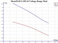
Voltage range mod - retain 1K voltage adjustment pot but vary R25 resistor

Well, I've acquired enough data to produce a graph of the various voltage ranges from different resistors at the R25 location.
S-150-24 Vloltage Range Mod.jpg

3.9K might be a bit high ... ?
4.1K looks better?
4.2V looks safest ... just below 12V to just above 14V ... ?

Fortunately, the strip lighting is built in 3 led (12V) segments.
I can cut a 3 led "test module" and raise voltage till it fails.
This, combined with a substantial safety margin, should indicate maximum sustainable voltage.
 
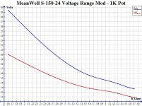
R25 Mod - Voltage range shifting.
Rather than adding a larger range pot to "widen-deepen" lower voltage capability, it is possible to change the R25 resistor which shifts the entire voltage range lower.
This graph should be reasonably accurate.

MW range 1K Pot.jpg

AND!!!
Very likely, lowering the resister value below 1.6K ohm should raise voltage range above 30V!
Will confirm with next mod.

Note - Adjusting low voltage below 11V produced occasional ... quirks, and so, is not recommended.
 
DrkAngel said:
R25 Mod - Voltage range shifting.

Very likely, lowering the resister value below 1.6K ohm should raise voltage range above 30V!
Will confirm with next mod.
R25 Mod ... successful ... mostly ...
I attached a 2K pot at the R25.
Then turned the voltage pot to highest voltage.
I was able to adjust R25 pot to 1.48K which output 34V, (oem specs at 28V), before a buzzing and voltage drop ensued.

The secondary voltage regulation is reputedly controlled by ZD1 (27V? Zener diode) right next to the blue 50V cap.
Ordered a few 33V & 36V Zener diodes, just to test ...
(Ordered 60V & 68V Zener diodes for my S-350-48 also)
Have I gone too far?

At least I haven't ordered 50V caps ... yet!

edit:
Update - Ordered the 50V caps.
 
DrkAngel said:
DrkAngel said:
R25 Mod - Voltage range shifting.
Ordered the 50V caps.
I have many MeanWell S-150-24's and would like to use them for as much as possible.
If I can push output to 36.45V I can use them to charge my 33.3V Li-ion & Lipo, most recent builds, 4.05V/bank "full" charge.
9 x 4.05V = 36.4V
9 x 4.10V = 36.9V
9 x 4.15V = 37.35V
9 x 4.20V = 37.8V

After exhausting S-150-24 potential ...

S-350-48
OEM voltage limit is ~54V.
15s @ 4.05 = 60.75V
15s @ 4.10 = 61.50V
15s @ 4.15 = 62.25V
15s @ 4.20 = 63.0V

S-100-12 - View attachment S-100-3.pdf

S-320-5 - View attachment S-320.pdf
I would like to stretch the voltage range for use in series with fixed voltage Server power supplies.
 
DrkAngel said:
DrkAngel said:
After I thought about it I realized that 12V LEDs would be designed to operate safely at "12V car voltages", cars charge at ~14V+.
4.3k resisters arrived.
Replaced R33 & R38 with a 1.1k, which should give me 10.5A.
Replaced the R25 with the 4.3k and got a reasonable 11.74V - 13.78V range.

Strip Light Test
5M 300 3528 leds

Rated:
"Working Input Voltage: 12VDC Working
Current/meter: 0.35-0.4A
Output power: 24W /5 Meter"

12V actual:
Current/meter: 0.24A
Output power: 15.3W /5 Meter

13.78V actual:
Current/meter: 0.29A
Output power: 20W /5 Meter

Looks like I will have to exceed 14V just to match "rated" power.
3.9k looks to be the proper resistor. ... still waiting on delivery ...

3.9k ohm, at R25, looks to be ideal for "12V" LED strip lighting!
Rated watt usage is attained between 14.4V and 14.8V as tested on various 3528, 5050 and 6530 SMD type strips.
12.4V - 14.8V range allows a 50-100% watt usage - a dimmer.

Speaking of dimmers, there are very small 12V 8 brightness level and multi flash mode controllers for less than $1.50. Simple and effective. Only "problem is an annoying "buzz" from MeanWell at lower brightness, apparently brightness is controlled by some form of PWM(?) - turning voltage on\off many times per second. But should be curable with a small cap (capacitor).
 
I added quality circuit board pictures in the ES Wiki articles for the MeanWell S-xxx-xx's:

S-150-5
S-150-12
S-150-15
S-150-24
S-320-5
S-320-12
S-350-24
S-350-48

More later
 
30-34V LED

I will mod a specimen for 30-34V high intensity LED modules.
10w, 20w, 30w, 50w, 100w modules available.

Swapping ZD1 to a 33V zener diode will allow proper voltage <30 to 33V+ range.
Replacing R25 with 1.4k resister should shift adjustable voltage to ~34V.
35V caps should be adequate. ... ?

OEM current should be adequate for led application of less than 120w.
 
Just found 24V 40mm fan.
Perfect for cooling the unit.

24V 40x10mm fan - $1.06

Will test 2 fans in series for 36-48V MeanWell use ... ordered 10 ...

At about 25V it seemed annoyingly loud , so ... I added a 47ohm 2w resistor in series.
Dropped voltage at fan to 21V and quieted to ... acceptable.
Fan placement appears optimal.

file.php
 
drkangel said
;.The downside is that if your cells are "unbalanced" they will recharge to the same "unbalanced" condition.
Unless...
You charge through a BMS\PCB\PC
So f I were to charge, say 60p( laptop testers) ,with the modded meanwell only, and run them up to the optimal voltage, then that voltage would be only the average of the individual cells volts?
 
douglashart said:
drkangel said
;.The downside is that if your cells are "unbalanced" they will recharge to the same "unbalanced" condition.
Unless...
You charge through a BMS\PCB\PC
So f I were to charge, say 60p( laptop testers) ,with the modded meanwell only, and run them up to the optimal voltage, then that voltage would be only the average of the individual cells volts?
No, 60P would be all identical, ... if positive connection on one end of the string and negative on the opposite. This eliminates line droppage.

Unbalanced refers to bulk charging in series - s.
 
Cheap - easy (470-500w) ≤84V 5.5A charger
63V @ ~7.5A
37.8V+ @ ≥8A

MeanWell, or any generic, 320(350)-48 ~6.5A 40-56V
+
Very available and easily modifiable
MeanWell S-150-24 ~6.3A 20-29V
=
7.8-5.5A (adjustable) 60-85V (adjustable) bulk charger! (w/current mod) - For 15s - 20s Li-ion = Lipo

+8-5.5A 9s - 20s w/voltage mod on both - very easy!
(Replace 1k voltage pots with 2k-5k - both units)

ES Wiki - MeanWell S-150-24

Run in series with any generic 320 or 350w 48V.
S-150-24 must be on the low end of voltage unless ground wire not used on either unit.
Might be voltage between cases of units - do not touch together till tested w/volt meter.
See MeanWell article "in series".

Easy (1000w) ≤84V 12.5A charger
 
DrkAngel said:
13s -20s 54-84V 500w CC\CV charger might be great ...
But many run at more moderate voltages.

My next MeanWell project will be a 7s-10s 27-42V 500w CC\CV charger
This will cover all of my present battery builds

Should be as simple, using:
MeanWell S-150-12
Generic S-350-24
Needs 20A Amp meter ...

Yes ... !
I will also, eventually, build and document a similar 9s-13s 500w CC\CV charger ...
 
i read all of the thread now and found similar issues like you when i wanted to adjust very low voltages. the whole unit starts buzzing and i can't reduce voltage below 15v. but what i would like to have is a bench power supply to adjust between 0-80v and current should be adjustable as well (that's the easy part). do you think this is doable with those units? i have a 60v unit with 100v caps which can easily be adjusted to 92v. so the high end is not the problem. the very low end is ... any ideas?
 
izeman said:
i read all of the thread now and found similar issues like you when i wanted to adjust very low voltages. the whole unit starts buzzing and i can't reduce voltage below 15v. but what i would like to have is a bench power supply to adjust between 0-80v and current should be adjustable as well (that's the easy part). do you think this is doable with those units? i have a 60v unit with 100v caps which can easily be adjusted to 92v. so the high end is not the problem. the very low end is ... any ideas?
I went with multiple units, waited till I found bargains.

Genuine MeanWells
Got S-150-5 for 0-40A of ~3-6V+, for bulk charging LiFe and Li-ions.
S-150-12 for 7-14V 0-20A
S-150-24 for 14-30V 0-10A
S-150-48 for 30-56V 0-5A

I did find a generic S-350-48 that adjusted from <4.1V to 56V+ but had no discernible current adjustment ... ?

Note on non-current adjustable switching power supplies:
Most switching power supplies copy the MeanWell "standard" of allowing 130% of rated current.
If voltage is reduced to <75%, current x voltage is reduced to "rated levels"-watts and unit should run continuously without overheat-failure.
And ...
Can be used as a current limiting unit when placed in series with other units.

Some units will work, but I have run into units that fault at current limit rather than regulate
See my most disappointing testing of a MeanWell - MeanWell S-240-48
 
izeman said:
so you say you didn't have any success getting super low voltages from the nominal 30v+ ps? or haven't you really tried and just gave up as i will soon ;)
"I did find a generic S-360-48 that adjusted from <4.1V to 56V+ but had no discernible current adjustment ... ?"
No brand or marking indicating manufacturer - MeanWell copy - design of shell, came with multi-turn pot.


Did not test adjusting below the 4.1V I was using for charging 18650 Li-ion, might have adjusted even lower.
Look for power supplies with multi-turn pots.
Some cheap manufactures might build 1 model with volt and amp adjustability and just adjust for different 24, 36, 48V models.

Wide range S-360-48 was merely labeled "S-360" on the front ... !
 
DrkAngel said:

MegaMod is great as a fixed multi-use charger ...
But my typical use sets it on the cool floor amidst wires etc. and is liable to have its dials bumped ... with "unwanted results".
So, I feel it advisable to build a version dedicated for charging specific battery packs.

file.php

Note - Optimal charged voltages determined by utilizing voltage areas of greatest energy densities

It appears that my 7s LiPo packs would be optimally charged at:
27.44V (3.92V/cell) 45% capacity - ~800% usable cycles 12Ah
28.14V (4.02V/cell) 65% capacity - ~400% usable cycles 17.35Ah
28.84V (4.12V/cell) 90% capacity - ~200% usable cycles 24Ah

Using a 3 position on/off/on switch, I can apply 3 separate resistance values at SVR1.
This will provide 3 separate charged voltages from a positive position switch.
Of course, I will install the Volt Amp meter for monitoring and confirmation.

Same switch method could also be applied to S-150-48 (or S-350-48) for various optimal charge voltages or quick change for 13s or 12s or 10s or 9s packs

Packs will be maintained at:
3.92V - for maximum life.
4.02V - for extra range during hot weather (4.10V+ reputed as very damaging in hot environs)
4.12V for maximum range during reasonable temperatures ~<90ºF
Additional charge level applied for extended cruising or trips.

Note - 4.12V optimized for hot weather if battery charged in cool area (<80ºF?) and discharged below 4.10V reasonably soon (before battery gets heated up.)
 
Bravo! I've found this thread by googling "mw s-150-24 charge battery", and I quickly realized I can't make this power supply do what I want in the time I have. That's the way it goes, lol. Thanks dude, you're awesome!

EDIT: Now that I think of it, by hooking a couple of power resistors up (Or one big power resistor), this shouldn't be too difficult.

Let's say we have a bunch of 1 ohm resistors (Like I do).

The battery is at 21V, power supply is at 24.6V, the volt difference is 3.6V.

With one ohm, the power dissipated is V^2/R or 3.6V^2/1 = 12.96W. A little much

Let's put two of them in series, W=V^2/R or (Since the volt is split between the two, the voltage is halved across each resistor) 1.8V^2/1 = 3.24W.

Three in series, 1.2^2/1 = 1.44W now that's more like it for continuous operation.

The amperage is V/R = 3.6V/3 ohm = 1.2A.

So, to up the amperage, just put more 3S 1 ohm resistors in parallel.

2x 3S 1 ohm resistor brances in parallel = 2.4A, 3x = 3.6A and so on.

I just happen to have 10, and a bunch of alligator clips, so I can actually do this.

I love those 1 ohm power resistors, so convenient.
 
Back
Top