Motorbike Motor

There are no good electric vs gas videos. That's why I am doing this project, to show an electric bike consistently beating the fastest
ice bikes.

Regarding the 100 foot pounds of torque and the 80+ hp. That is the capability of the system. The maximum throttle will be the ratio
between the front wheel and the rear wheel adjustable from 101 percent to 200 percent (twice the rotation). A tires' grip reduces with
too much over spin. The maximum rate can be adjusted with a knob at any time to dial in the maximum rear wheel slippage.
Riders will want to set their own level according to their riding style and conditions.
 
Electric v gas search for toolman2 video... Following your motor build with interest best of luck

KiM
 
Just waiting for the Somaloy Prototyping Material blanks. It is supposed to crumble easily so machining and winding
36 turns of .093" square motor wire around the cores may be difficult. A custom winding machine will need to be built.
 
I just received the Somaloy prototype core material. It just feels like a chunk of steel. I was expecting some weird material because the
iron particles are supposed to be coated and insulated from each other and then compressed with a binder and cooked, but it just looks
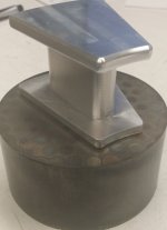
like iron. I have to machine it to the shape of the aluminum piece on top. It should be interesting.

20141029_152803 (5).jpg
 
motomoto,
When we looked at Somoloy, we only considered using machined wedge faces for the coils where the coil mandrel was made from laminated steel and the wedge faces were notched to bond to the coil mandrels. The shape you are trying to machine will not be easy because the Somoloy is very brittle and it takes special types of cutters, speeds, coolant, etc. Then, when you had the Somoloy wedge faces bonded to the coil mandrels and preferably installed in the stator structure, you could have designed a grinding fixture, placed the stator in a lathe and rotated the stator and ground the wedge faces so they were all perfectly flat. I wish you a lot of luck with the approach you are taking for a one-of-a-kind motor.

The rotor can also be fabricated by using a 3D printed form to space the magnets and consider using a glass plate as the base of the epoxy bonding fixture. It is a bit hard to explain because I view it as a multi step process of creating a bonded rotor. The 3D form (say PLA filament) can be very easily removed (acetone or such) from the rotor face. Under the glass plate base, you may want to place a matrix of rod magnets to ensure that your rotor magnets stay firmly attracted to the glass base. I will be curious to see how all this turns out for you.

We will be using T shaped magnets instead of wedge shaped magnets simply because it is a much cheaper approach and you can still get a pretty high ring area fill factor (80%). You will find that trying to make a T shaped magnet from two block magnets is not trivial (they want to repel each other when you try to bond them together). One thing we already discovered (by accident) is that most one component epoxies attack the nickel plating at the bonding interface (nickel plating can become debonded from the neo). Permabond is providing a sample they think may work. Finally, consider closing the magnet field of the layer of magnets on the rotor with a second layer just behind and between the first layer and the back iron. Just some things for you to consider. Isn't designing motors fun?
kenkad
 
I am not really designing a motor. Just executing the fabrication of a motor already designed. I know where I am stupid.

Thanks for the advice. I am going to try the one piece machining and if that doesn't work I am going to do a 3 piece
like the YASA article I am going off of. They leave a lot to the imagination on construction, but I think I have it worked out.
 
motomoto said:
I am going to do a 3 piece like the YASA article I am going off of.
I would suggest doing a 2-piece (T-style including one face and half the core) that can be more easily machined if you go away from the solid construction. This would allow you to wind the copper separately and then insert the half-cores into the form-wound coil.

motomoto said:
They leave a lot to the imagination on construction, but I think I have it worked out.
I think a lot of their value as a R&D company probably comes from understanding how much you have to pre-flare the rotor to not have the magnets end up rubbing on the core materials. Also, the structure required to transmit that torque from individual pole pieces to some frame mount seems to be the tricky bit, not to mention how to cool the windings to get a good amount of power out of it. Are you going to pot the whole stator assembly when you're done?
 
halcyon_m,
Since no one else want to take a bite of the apple :D , I will. Your comment was

I think a lot of their value as a R&D company probably comes from understanding how much you have to pre-flare the rotor to not have the magnets end up rubbing on the core materials.

which I find puzzling. In our AF BLDC design, the coil wiring exits one end of the hollow stator shaft. The two rotors are on either side of the stator (on appropriate bearings of course on the hollow shaft) and thus are tightly spaced on the hollow shaft but there is also a cylindrical spacer that separates the outer edges of the rotor and is attached to the rotors. This provides the ability to 'skew' the rotors relative to each other (~5 degrees or so) if testing indicates this to be desirable and locks the rotors together. Finally one rotor has the drive shaft exiting the overall motor enclosure. So then the question is what is all this 'pre-flare' about? Yes, I understand that as the rotors get larger in diameter and the attraction get very very large, there will be deflection in the rotors. That is all part of the design process and can be accounted for in the stress analysis of most 3D CAD packages. I believe you have to accommodate at least 0.1-0.15mm deflection on a .7mm air gap, or some such decision.
kenkad
 
I understand there is a lot of pushing and pulling going on when the current through the coils is high, but isn't there an equal amount
of pushing and pulling? I am still trying to get the idea of 3 phases going positive and negative thousands of times a minute. If someone
wants to set me straight on what is really going on, I am all ears.
 
motomoto,
I have some of the published papers and info on the YASA design. I have never seen any detailed design drawings. Do you have such drawings? Better yet, would be the 3D CAD model. I would not wish anyone to be disappointed copying a design that is not fully detailed and thus end up with a marginally usable device. I was just asking why there would be 'pre-flare' on the rotor face. If someone knows this, maybe they have the 3D CAD design. I personally would and do question the minute details of anyone's design that is going to take a very great deal of effort to replicate. Just trying to give you some heads-up.
kenkad
 
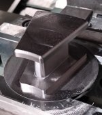
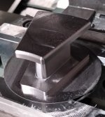
I got the Somaloy cores about done, but I have to make a special fixture to wind the copper.

It's quite an engineering project in itself.

core machined (975x1090).jpg
 
Thanks Man.

I wrote early on;

I have considered 2 of the 1/4" ones on top of the other to cut down on eddy
current loss but the extra magnet would start .31" away from the core face at the closest and I am not sure if it is worth it

The first part of the sentence is bulls!@#, but the last part is true.

I could always make the magnet plates with twice the magnets if that makes it faster and work better. It would add another 1.68 lbs
of spinning mass, but that might be a good thing.
 
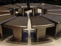
20141112_180429 (2).jpg

I am getting ready to wind these Somaloy cores.

Do I need to cover the areas where the motor wire touches the core with slot lining material?
 
I think so, but wait for the master's opinion.

In the mean time, beautiful work! Are you a machinist or mechanical engineer?
Can you post video of the machining processes?

Chris
 
I try to be a decent machinist. Engineer? hardly. But I do have a machine shop and consider myself the
luckiest guy in the world. If I can make this motor and it has some decent power, I will be so stoked.
There are good machining videos on Youtube I am sure.
 
Kim,
From here it looks like you have no sharp corners that would put stress on the copper as you wrap it...(you were doing square wire?)
If you have any concerns, it would never hurt to put a thin layer of nomex between the wire & core.

it is good practice to re-lacquer the windings once wrapped to lock them in place, avoiding any vibration induced chaffing & possible short-circut's

very exciting stuff your doing.....your scale is x10 of my motor project.
 
motomoto,
Looks as if you used a vacuum hold down plate, maybe even on a rotary table (based on the pattern on the face of the coil form). Can you post a JPG of this fixture? I am sure alot of members who have a good DRO knee mill might want to try this when they see your fixturing. A full CNC mill would obviously be much easier.
kenkad
 
Kenkad,
Nothing fancy holding the material. I just carved a round pocket in some aluminum vice jaws.
It is a CNC mill for sure. I took .030" cuts because the material is a little brittle and I didn't
want any issues.

core machined (975x1090).jpg

Thud,
Thanks for the input. I have been researching electrical insulating paper that can be infused with
motor varnish. I think I will get some.
 
Arlo's signature mentions a guy who has nomex.
He still had some last time I checked.
Chris
 
Normally you need the Nomex paper to keep the wire from shorting on sharp edges of the stator laminations.
Your cores are very smooth looking, so you may be good without any. Those are the nicest looking stator cores I've ever seen. I thought Metglas would be good stuff for cores too, but I don't think you can machine it like that.

+1 on the laquer. The laquer just keeps the windings in place so they don't vibrate against each other and rub through the insulation. There can be significant forces on the wires. Laquer is easy and makes rewinding a burnt coil still possible. I've seen motors that use epoxy on the windings too. That would be tough to rework. Either one helps a little with heat transfer. Downside is your motor will stink like laquer the first few times it gets warm.
 
This guy called me up today from Herold and Mielenz in Sacramento and said he would love to help me
with my motor project.

We will get together next week.

Here is some info on the company.

unnamed.jpg

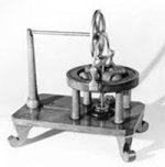
HEROLD & MIELENZ, INC. didn't invent the first electric motor, but our great, great, great grandfather did! The Mielenz family is a direct descendant of Thomas Davenport, credited with inventing the first commercially successful electric motor in 1834.

A blacksmith in Brandon, Vermont, Davenport began experimenting with electromagnets in 1831 and by 1834 he had constructed his first electric motor, pictured above. Operated by battery, Davenport used his electric motor to propel a small car around a circular track, the first recorded instance of an electric railroad.

Davenport later established a workshop in New York City and began a publication on electromagnetism and mechanics printed on a press powered by the electric motor he invented.

Since 1945 we have worked closely with OEM'S, industrial plants, and processing companies, solving their drive and motor problems and servicing their equipment needs.

Each Herold & Mielenz, Inc. employee is a qualified technician, educated in his field, experienced through years of work in the industry and dedicated to making each product application and project a product of true craftsmanship.

It is our understanding of customer needs, attention to detail and our reputation of standing behind our work that has made Herold & Mielenz, Inc. the strong force that it is in the field today.

When you need electric motor drive expertise coupled with integrity, call Herold & Mielenz, Inc.
 
Bump....anxious for a lil update.
Thx.
 
Back
Top