
You are using an out of date browser. It may not display this or other websites correctly.
You should upgrade or use an alternative browser.
You should upgrade or use an alternative browser.
Compact Field Oriented Controller, ASI + Grin, limited run
- Thread starter justin_le
- Start date
district9prawn
1 kW
Has sensorless generally worked well across a range of different motor types?
parabellum
1 MW
riba2233 said:Thanks for the answer!Do you have the info on the max erpm?
circuit said:Since you mentioned these, how much is BAC1000 or BAC3000?
They are specified 20kHz and 550$ (US$?) each.
http://www.tecknowledgey.com/accelerated-systems-bac3000-brushless-dc-controller.html
P.S. BAC3000
riba2233 said:Thanks for the answer!
I don't have a hard number since we haven't been able to hit it with any of the motors around our shop. On the RC skateboard motors, we were running a 7 pole pair motor in 83mm wheel at 70kph, = 4650 rpm = 32k erpm, sensorless, no problems. I'll try to get a more concrete answer though. What erpm are you specifically needing to run at?
district9prawn said:Has sensorless generally worked well across a range of different motor types?
Generally yes. We had some funny issues running the Cycle Stoker sensorless from a standstill when there was a bit of windup and elasticity in the chain drive which confused the open-loop self starting routine in a funny way that wasn't present at all if the exact same motor was used in a hub drive. But our experience with sensorless mode for RC motors, direct drive hubs, and geared hubs has all been fine, although the necessary parameter tuning for sensorless start can be confusing. That's why it's for technically inclined users at this stage.
Justin, can you tell us how sensorless start did work in comparison to sensored start (under load)?
I'm a bit confused what the 95% efficieny declaration means. Is it the max efficiency the motor could be driven, or is it controller efficiency?
I'm a bit confused what the 95% efficieny declaration means. Is it the max efficiency the motor could be driven, or is it controller efficiency?
robbie
1 W
- Joined
- Sep 28, 2012
- Messages
- 50
Hey folks,
I'm happy to see that the BAC500+ is available and has started to arrive in your hands!
The software suite for the BAC500+ is called BacDoor. We currently only have a version available for Windows (it seemed to install fine on machines from XP to 7). It is quite an impressive suite that allows for a miryad of fine tuning options to dial in your desired performance for cool projects such as a high rpm direct drive motor in sensorless with regen, or a simple geared system with nice torque control. The sheer number of parameters available for adjustment is staggering, however, with the manual provided by ASI and some guidelines from us at Grin you should be able to get things running smoothly. The manual is for a slightly older version of firmware, however it is the best resource available at the moment.
We're going to be shipping the BAC500+ with BACdoor version 1.5 (build 10.30319.1) as provided by ASI. As new software arrives and is tested, we'll be updating the files available.
The files are located here http://www.ebikes.ca/shop/ebike-parts/controllers/c-bac500.html under the "Additional Information" tab. Also see Justin's post above.
I'd also like to give some general information here regarding the usage of BacDoor.
When programming your system with BacDoor the system is live - you will be changing parameters that could cause the motor to start turning - so make sure you have whatever driven wheel or system free from snags or hands to get caught in. This is especially prudent during motor parameter discovery as the motor will be spun and can only be interupted by removing power. So put your bike in a stand, put the motor in a vice separately or lift the wheel etc.
Download and install the files from the .zip and you'll be greeted with a screen like this when you launch the program;

The software has a general mouse-over feature that will give you further details on most of the parameters. Hover over the description text not the input box.
BacDoor interfaces with the controller via a TRS RS-232 cable (the same one for a CA3 or Satiator works fine) - the default values for baud rate (115200) and address (1) should be left unmodified. The general layout has a write/save area where you specify parameters and write them to the controller, a display pane that shows measured or calculated parameters from the controller (you can press read or you can poll the display pane to give a live update of the measured parameters) and a temporary write pane (this is rarely used). You must have the unit powered by your battery and turned on to communicate with the software. Press the connect button in the Network pane on the right.
Programming the parameters is done by entering your value and either pressing enter or pressing write at the bottom of the write/save pane. These parameters are then temporarily saved to the controller. To permanently save the parameters, you *must* select Parameter -> Save to Flash from the top menu bar. Losing power before doing so will cause the parameter changes to vanish.
Generally when setting up a vehicle with the BacDoor software, you'll want to move from left to right.
1. Start at Peripheral Selection and complete all of your settings here.
2. Then move to Peripheral Configuration
3. Finally move to Protection and Fault Thresholds
The System Debug and Controller Debug areas have mostly non-modifiable values, but are interesting to investigate. Don't change anything you don't understand.
Instead of using direct values, BacDoor instead uses % ratings for a number of parameters.
Here's an example. I want to set my battery voltage and make sure regen doesn't damage my battery, and that when the battery is low it will not allow power to the motor.
Peripheral Selection -> Motor Nameplate Ratings -> Rated System Voltage The rated system voltage here can be set as your maximum battery voltage hot off the charger, or to your nominal battery voltage. However, under Protection and Fault Thresholds -> Battery you will see a number of other parameters that are all based off the rated system voltage that you'll need to account for to ensure that the controller doesn't enter a fault state unnecessarily. Of particular importance are the slow and fast over/under voltage thresholds - the low and high battery foldback voltages are a similar feature to that of the CA's low voltage limit wherein it will begin to limit power (or regen) as the battery voltage enters these programmed regions.
The rated system voltage also affects your battery current limit as this is calculated by your rated motor power, and the rated system voltage. The controller will either try and limit your battery current based on the rated motor power or the rated battery current whichever comes first. I typically aim to set a battery current limit instead of a battery power limit, so I will set my rated system voltage to my fully charged battery voltage and choose a power rating that will yield say 25A, and then I set my battery current limit to 100% of rated. The Regeneration battery current limit is also based on the power/voltage relationship.
I'll make some more posts with cool features on the BacDoor software - but lets go over a basic direct drive motor setup - assuming you're using a CA3.
*edit: changed image to .jpg for inline view
I'm happy to see that the BAC500+ is available and has started to arrive in your hands!
The software suite for the BAC500+ is called BacDoor. We currently only have a version available for Windows (it seemed to install fine on machines from XP to 7). It is quite an impressive suite that allows for a miryad of fine tuning options to dial in your desired performance for cool projects such as a high rpm direct drive motor in sensorless with regen, or a simple geared system with nice torque control. The sheer number of parameters available for adjustment is staggering, however, with the manual provided by ASI and some guidelines from us at Grin you should be able to get things running smoothly. The manual is for a slightly older version of firmware, however it is the best resource available at the moment.
We're going to be shipping the BAC500+ with BACdoor version 1.5 (build 10.30319.1) as provided by ASI. As new software arrives and is tested, we'll be updating the files available.
The files are located here http://www.ebikes.ca/shop/ebike-parts/controllers/c-bac500.html under the "Additional Information" tab. Also see Justin's post above.
I'd also like to give some general information here regarding the usage of BacDoor.
When programming your system with BacDoor the system is live - you will be changing parameters that could cause the motor to start turning - so make sure you have whatever driven wheel or system free from snags or hands to get caught in. This is especially prudent during motor parameter discovery as the motor will be spun and can only be interupted by removing power. So put your bike in a stand, put the motor in a vice separately or lift the wheel etc.
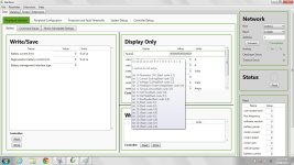
Download and install the files from the .zip and you'll be greeted with a screen like this when you launch the program;
The software has a general mouse-over feature that will give you further details on most of the parameters. Hover over the description text not the input box.
BacDoor interfaces with the controller via a TRS RS-232 cable (the same one for a CA3 or Satiator works fine) - the default values for baud rate (115200) and address (1) should be left unmodified. The general layout has a write/save area where you specify parameters and write them to the controller, a display pane that shows measured or calculated parameters from the controller (you can press read or you can poll the display pane to give a live update of the measured parameters) and a temporary write pane (this is rarely used). You must have the unit powered by your battery and turned on to communicate with the software. Press the connect button in the Network pane on the right.
Programming the parameters is done by entering your value and either pressing enter or pressing write at the bottom of the write/save pane. These parameters are then temporarily saved to the controller. To permanently save the parameters, you *must* select Parameter -> Save to Flash from the top menu bar. Losing power before doing so will cause the parameter changes to vanish.
Generally when setting up a vehicle with the BacDoor software, you'll want to move from left to right.
1. Start at Peripheral Selection and complete all of your settings here.
2. Then move to Peripheral Configuration
3. Finally move to Protection and Fault Thresholds
The System Debug and Controller Debug areas have mostly non-modifiable values, but are interesting to investigate. Don't change anything you don't understand.
Instead of using direct values, BacDoor instead uses % ratings for a number of parameters.
Here's an example. I want to set my battery voltage and make sure regen doesn't damage my battery, and that when the battery is low it will not allow power to the motor.
Peripheral Selection -> Motor Nameplate Ratings -> Rated System Voltage The rated system voltage here can be set as your maximum battery voltage hot off the charger, or to your nominal battery voltage. However, under Protection and Fault Thresholds -> Battery you will see a number of other parameters that are all based off the rated system voltage that you'll need to account for to ensure that the controller doesn't enter a fault state unnecessarily. Of particular importance are the slow and fast over/under voltage thresholds - the low and high battery foldback voltages are a similar feature to that of the CA's low voltage limit wherein it will begin to limit power (or regen) as the battery voltage enters these programmed regions.
The rated system voltage also affects your battery current limit as this is calculated by your rated motor power, and the rated system voltage. The controller will either try and limit your battery current based on the rated motor power or the rated battery current whichever comes first. I typically aim to set a battery current limit instead of a battery power limit, so I will set my rated system voltage to my fully charged battery voltage and choose a power rating that will yield say 25A, and then I set my battery current limit to 100% of rated. The Regeneration battery current limit is also based on the power/voltage relationship.
I'll make some more posts with cool features on the BacDoor software - but lets go over a basic direct drive motor setup - assuming you're using a CA3.
*edit: changed image to .jpg for inline view
Attachments
justin_le said:I don't have a hard number since we haven't been able to hit it with any of the motors around our shop. On the RC skateboard motors, we were running a 7 pole pair motor in 83mm wheel at 70kph, = 4650 rpm = 32k erpm, sensorless, no problems. I'll try to get a more concrete answer though. What erpm are you specifically needing to run at?
Thanks! I was aiming for that same 7 pole pairs outrunner, something like 80-85 to be run at 9000 rpm, so about 63000 erpm. I know that kelly has 70000 erpm option at 16 khz pwm, so if your controller has 20 khz pwm, I guess that could be possible.
robbie
1 W
- Joined
- Sep 28, 2012
- Messages
- 50
Using a CA3 - lets go over some basic setup stuff to get you running. Don't forget to use the Paremeter -> Save to Flash if you want to save your inputs in case of a fault or battery disconnect.
Peripheral Selection -> Battery
Battery Current Limit: 100%
Regeneration Battery Current Limit: 25%
Battery management interface type: 0
Peripheral Selection -> Command Inputs
Control command source: 1 (this sets the input source to be the analogue throttle signal)
Features: 0000000001010000 (this enables regen braking and has a stall shutoff) If you're using a geared motor, you do not need to set the 4th bit to 1, it can remain at 0
Every other parameter should be 0.
Peripheral Selection -> Motor Nameplate Ratings
Rated motor current: 60 (this will self impose a maximum of 73A)
Rated motor speed: Set this to your maximum unloaded RPM
Rated system voltage: Set to fully charged battery voltage
Rated motor power: Set to desired battery current limit * rated system voltage (ex. 25A at 55V = 1375 for a 25A 48V system)
Motor position sensor type: Mouse over for description and settings we can set this later when we configure the motor peripheral
Motor pole pairs: Put in your motor pole pairs
Gear ratio: if you have a geared motor put in the ratio, if not, put in 1.
Peripheral Configuration -> Throttle
Throttle open voltage: 3.5V (you can set this to whatever, but leaving it at 3.5 means you can configure your CA3 and also use a regular plug in throttle directly into the controller if needed)
Throttle closed voltage: 1.0
Positive motoring torque ramp: 200ms
Negative motoring torque ramp: 200ms - change the torque ramps around to get the desired "punch" or smoothness
Throttle fault range: 1.1 (leave this at 1.1 so that the throttle signal can be pulled to ground for regen purposes without causing a fault)
Peripheral Configuration -> Brakes
Cutoff Brake Sensor Type: 0 (you can use pins 2 and 4 on the 4pin JST to enable cut-off)
Analogue brake closed voltage: 0.8V
Analogue brake open voltage: 0.1V
Maximum braking torque: 30% (This is a % of your phase current as defined under the peripheral selection)
High battery foldback start: 105%
High battery foldback end: 110%
ramp rates are self explanatory
Now is where you decide for sensorless or sensored.
The first thing to do is to run the motor parameter discovery function inside the controller - you'll want your motor supported so that it can't run away and so that nothing could get caught in the chain etc if the motor spins backwards. The motor will be spinning and cannot be stopped save for the end of the test or disconnecting the battery.
First you'll want to poll the parameters;
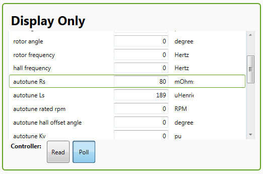
The poll button should be blue.
Next we'll discover the motor resistance and inductance to be entered in the Rs and Ls.
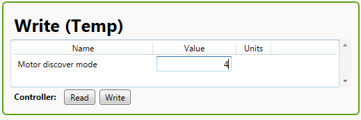
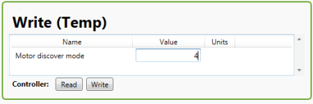
In the Write (Temp) section bottom right, you'll enter 4 in the Motor Discovery Mode and press enter. The motor will make a buzz and whine as it pulses high frequency current into the windings.
After this finishes, you should see the autotune Rs and autotune Ls fields populate under the display only tab. Simply input the values into the Write/Save section and press enter or write.
Next we'll configure the hall sector mapping - during this the motor WILL turn so be prepared for it to spin backwards or forwards for about 15 seconds. It will also spin the motor at 1/2 the rated RPM as setup previously. Be sure that the polling is still enabled on Display Only and enter "3". The motor will turn for about 15 seconds, and the autotune hall sector fields will fill in. Simply copy the values over to the Write/Save press enter for each, or write with the button at the bottom. If your motor spins backwards, either swap a pair of phases and redo the hall sensor detection or enter 1 into the furthest right 0 of the Motor features parameter under Write/Save.
The last thing to do is to set the Motor position sensor type to either 0 or 1.
Everything for a sensored motor should work now, try your throttle with the wheel off the ground!
For sensorless, select the Peripheral Configuration -> Basic Motor (Sensorless) tab.
First you'll want to set the Motor position sensor type to 2.
The procedure for discovering the resistance (Rs) and inductance (Ls) is the same as above. The only difference with sensorless operation is that you'll want to tune the following settings:
Sensorless open loop starting current: 0.3
Sensorless open loop freq ramp time: 200ms
Sensorless closed loop enable freq: 20Hz
You'll want to do this by starting with the default values and tweaking - these values will depend on your setup.
Peripheral Selection -> Battery
Battery Current Limit: 100%
Regeneration Battery Current Limit: 25%
Battery management interface type: 0
Peripheral Selection -> Command Inputs
Control command source: 1 (this sets the input source to be the analogue throttle signal)
Features: 0000000001010000 (this enables regen braking and has a stall shutoff) If you're using a geared motor, you do not need to set the 4th bit to 1, it can remain at 0
Every other parameter should be 0.
Peripheral Selection -> Motor Nameplate Ratings
Rated motor current: 60 (this will self impose a maximum of 73A)
Rated motor speed: Set this to your maximum unloaded RPM
Rated system voltage: Set to fully charged battery voltage
Rated motor power: Set to desired battery current limit * rated system voltage (ex. 25A at 55V = 1375 for a 25A 48V system)
Motor position sensor type: Mouse over for description and settings we can set this later when we configure the motor peripheral
Motor pole pairs: Put in your motor pole pairs
Gear ratio: if you have a geared motor put in the ratio, if not, put in 1.
Peripheral Configuration -> Throttle
Throttle open voltage: 3.5V (you can set this to whatever, but leaving it at 3.5 means you can configure your CA3 and also use a regular plug in throttle directly into the controller if needed)
Throttle closed voltage: 1.0
Positive motoring torque ramp: 200ms
Negative motoring torque ramp: 200ms - change the torque ramps around to get the desired "punch" or smoothness
Throttle fault range: 1.1 (leave this at 1.1 so that the throttle signal can be pulled to ground for regen purposes without causing a fault)
Peripheral Configuration -> Brakes
Cutoff Brake Sensor Type: 0 (you can use pins 2 and 4 on the 4pin JST to enable cut-off)
Analogue brake closed voltage: 0.8V
Analogue brake open voltage: 0.1V
Maximum braking torque: 30% (This is a % of your phase current as defined under the peripheral selection)
High battery foldback start: 105%
High battery foldback end: 110%
ramp rates are self explanatory
Now is where you decide for sensorless or sensored.
The first thing to do is to run the motor parameter discovery function inside the controller - you'll want your motor supported so that it can't run away and so that nothing could get caught in the chain etc if the motor spins backwards. The motor will be spinning and cannot be stopped save for the end of the test or disconnecting the battery.
First you'll want to poll the parameters;
The poll button should be blue.
Next we'll discover the motor resistance and inductance to be entered in the Rs and Ls.
In the Write (Temp) section bottom right, you'll enter 4 in the Motor Discovery Mode and press enter. The motor will make a buzz and whine as it pulses high frequency current into the windings.
After this finishes, you should see the autotune Rs and autotune Ls fields populate under the display only tab. Simply input the values into the Write/Save section and press enter or write.
Next we'll configure the hall sector mapping - during this the motor WILL turn so be prepared for it to spin backwards or forwards for about 15 seconds. It will also spin the motor at 1/2 the rated RPM as setup previously. Be sure that the polling is still enabled on Display Only and enter "3". The motor will turn for about 15 seconds, and the autotune hall sector fields will fill in. Simply copy the values over to the Write/Save press enter for each, or write with the button at the bottom. If your motor spins backwards, either swap a pair of phases and redo the hall sensor detection or enter 1 into the furthest right 0 of the Motor features parameter under Write/Save.
The last thing to do is to set the Motor position sensor type to either 0 or 1.
Everything for a sensored motor should work now, try your throttle with the wheel off the ground!
For sensorless, select the Peripheral Configuration -> Basic Motor (Sensorless) tab.
First you'll want to set the Motor position sensor type to 2.
The procedure for discovering the resistance (Rs) and inductance (Ls) is the same as above. The only difference with sensorless operation is that you'll want to tune the following settings:
Sensorless open loop starting current: 0.3
Sensorless open loop freq ramp time: 200ms
Sensorless closed loop enable freq: 20Hz
You'll want to do this by starting with the default values and tweaking - these values will depend on your setup.
Attachments

robbie
1 W
- Joined
- Sep 28, 2012
- Messages
- 50
One last post!
One awesome feature of the BacDoor is the customize the displayed parameters - you can right click in any of the panes and select Add Parameter.
This will pop up a giant list of parameters for you to add to the pane. Not all are editable. Not all can be polled, but it does allow quicker configuration for some things.
You can mouse over the parameter to get a description.
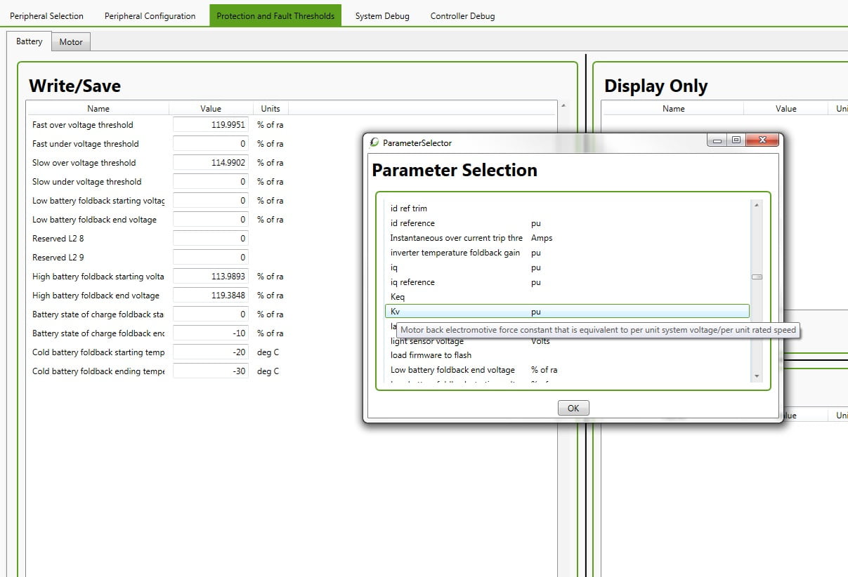
Here you can also see the battery threshold settings. Be sure to set them based on what you set your nominal system voltage as.
48V nominal means your over voltage should be at ~60V so if you put 48V in the rated system, you need to set Fast OV as 125%, where as 55V in rated system youd want to set it as 109%. Keep this in mind with any of the % rated or pu values.
The low and high battery foldback settings are to limit power on discharge and regen and should be set such that they are within the bounds of the over and under voltage thresholds.
One awesome feature of the BacDoor is the customize the displayed parameters - you can right click in any of the panes and select Add Parameter.
This will pop up a giant list of parameters for you to add to the pane. Not all are editable. Not all can be polled, but it does allow quicker configuration for some things.
You can mouse over the parameter to get a description.
Here you can also see the battery threshold settings. Be sure to set them based on what you set your nominal system voltage as.
48V nominal means your over voltage should be at ~60V so if you put 48V in the rated system, you need to set Fast OV as 125%, where as 55V in rated system youd want to set it as 109%. Keep this in mind with any of the % rated or pu values.
The low and high battery foldback settings are to limit power on discharge and regen and should be set such that they are within the bounds of the over and under voltage thresholds.
Attachments
robbie
1 W
- Joined
- Sep 28, 2012
- Messages
- 50
district9prawn said:Has sensorless generally worked well across a range of different motor types?
Generally yes. I've found that geared motors with low inductance (such as the eZee motors) require a bit more fine tuning of the sensorless motor parameters. We've had success with all direct drive motors from small high rpm outrider RC motors... to small dd motors and even to larger HS series motors running sensorless.
johnrobholmes
10 MW
Thanks for the walkthrough Robbie. I'll see what we can get out of sensorless tuning a bafang BPM, then try sensored if it's being tricky.
Alan B
100 GW
Great project Justin,
What is the top speed loss compared to the usual trapezoidal controller on a standard hubmotor?
Does the torque throttle work smoothly on a geared hubmotor? Some controllers seem to have trouble with smooth control of gearmotors with internal freewheels so they get "behind" the speed of the wheel when coasting.
Thanks in advance,
Alan B said:Great project Justin,
What is the top speed loss compared to the usual trapezoidal controller on a standard hubmotor?
Based on controller temperature studies I was concluding on the order of 25-30 watts of controller losses when it was running effectively full power for a 1000W system (40A @ 48V, see attached pdf). I do not have a similar number for a trapezoidal drive controller running in exactly the same conditions, but that is an experiment we could and probably should run in order to find out. Plus we just got a high-end Flir thermal camera over the weekend and what better project to put it to use
Does the torque throttle work smoothly on a geared hubmotor? Some controllers seem to have trouble with smooth control of gearmotors with internal freewheels so they get "behind" the speed of the wheel when coasting.
When it is engaged the torque throttle is uber-smooth. But yes the presence of the internal one-way clutch definitely causes self-start sensorless startup confusion with most controllers since the system inertia is totally different when it is engaged to the bike wheel and when it isn't. In this one you can tune all of the all of the open-loop ramp up parameters to make it work perfectly, but if you don't tune it right then it can easily trip into a fault state right when you first hit the throttle. So please everyone be aware it is not a "plug and play" universal controller, it is more like "plug, tune, and play", and you need to know a thing or two about BLDC motors and controllers in order to do the tuning.
Attachments
Alan B
100 GW
Thanks Justin,
I was wondering about the top speed loss, not the efficiency difference. I switched from a trapezoidal to a sine wave controller (Xie Chang to Sabvoton) on my Cromotor bike and lost about 10% of the top speed (with no field weakening). Just curious if this is similar. The only bike I have that might work for this has a fairly low top speed, wondering how much I might lose by this.
Thanks!
johnrobholmes
10 MW
With the ability to field weaken you can get the speed back easily but since this is a FOC and not a "dumb" sine wave controller, a speed loss may not occur
Alan B
100 GW
Yes, but. The efficiency suffers when you use field weakening. The bike I would put this on is intended a recumbent that is intended to be efficient for long range, there is a 100 mile ride and a 2KWH limit I want to be able to participate in, so in that case I would probably not want to use FW. The speed loss I see on my CroBorg is a bit over 10% from Trap to Sine. Was curious how much this one is (it might be the same, or not, depending on how closely they stick to a sine wave). Some sine wave controllers seem to play a bit loose with the waveform when they approach maximum speed.
johnrobholmes
10 MW
In theory this controller should output something very close to the bEMF of the cromotor in sensorless mode. Maybe sensored too. So if its more trap shaped bEMF you will get closer to trap drive and your top speed won't be affected much compared to a 6 step controller.
Also very important is the commutation dead time during full duty . The Sabvaton may have a more generous delay period between steps so it isn't applying as much average voltage as the Xie Chang. I would say it is impossible to guess on this controller from Grin without an actual test on a cromotor. But if they have tested speeds on a 9c with the BAC500 VS the xie chang it could have a similar result, but that assumes the bEMF is similar between the the 9c and Cromotor.
Also very important is the commutation dead time during full duty . The Sabvaton may have a more generous delay period between steps so it isn't applying as much average voltage as the Xie Chang. I would say it is impossible to guess on this controller from Grin without an actual test on a cromotor. But if they have tested speeds on a 9c with the BAC500 VS the xie chang it could have a similar result, but that assumes the bEMF is similar between the the 9c and Cromotor.
Alan B
100 GW
I would use it on a BMC gearmotor rather than the Cromotor, the Sabvoton is a good fit to that.
The speed reduction ratio on any trapezoidal BMF motor would be a rough guide, percentage wise. At least a starting point.
You are running one of these, how was your top speed affected compared to a Trap controller?
The speed reduction ratio on any trapezoidal BMF motor would be a rough guide, percentage wise. At least a starting point.
You are running one of these, how was your top speed affected compared to a Trap controller?
johnrobholmes
10 MW
I haven't gotten my BAC running yet, but I'm running a sine wave controller on my most used and most likely bike to get this one.
does FOC controller really change the wave form from sine to whatever waveform of back EMF?
as for the speed i understand it like this: a sine-wave has less area under the curve than a square, so less RMS phase voltage flows to the motor therefore less speed.
flux weakening works like an electrical pre -ignition (or timing correction in degree). right? The controller does switch earlier than usual to the next phase (coil) and this results in more speed.
Alan B
100 GW
FOC is usually sine wave, RMS = 0.707 * Peak.
FOC puts current in/out of all three motor wires to create a rotating field at the optimal angle for torque. Field Weakening also puts current into the vector perpendicular to the torque current to oppose the permanent magnets in the motor, weakening their effective field. This results in less back EMF, higher speed and less torque from the motor, plus the current used to effect this adds to the inefficiency of the motor in that mode. So do it if you need to but realize it costs efficiency.
FOC puts current in/out of all three motor wires to create a rotating field at the optimal angle for torque. Field Weakening also puts current into the vector perpendicular to the torque current to oppose the permanent magnets in the motor, weakening their effective field. This results in less back EMF, higher speed and less torque from the motor, plus the current used to effect this adds to the inefficiency of the motor in that mode. So do it if you need to but realize it costs efficiency.
oatnet
1 MW
Must... Resist... The... Urge... To... Start... a... Project... With... This...  :lol:
:lol:
Similar threads
- Replies
- 11
- Views
- 1,815
- Replies
- 10
- Views
- 1,381
-
- Locked
- Replies
- 120
- Views
- 20,011