Compact Field Oriented Controller, ASI + Grin, limited run

okashira said:
\/ampa said:
okashira said:
Can you do one more at ~13 amps? I would LOVE to see how things look at a partial relative load.
Since they run different voltage now. Its better to say another dyno test with 500W power draw from both.
That would be fine also.

Here it is. The infineon trapezoidal controller was at 48.0V with a 12.0 current limit set via a CA, wile the BAC500 FOC controller was run at 51.4V with an 11.2A current limit. So 575 watt input power limit in both cases, and the same unloaded RPM in both cases. The CA had a much easier time regulating the battery current draw on the FOC with it's torque throttle, while the infineon controller had a fair amount of feedback oscillation just as it was transitioning to the amps limit around 420 rpm, and you can see the corresponding scattering of torque and power data..


Overall, the performances are quite close near the top end of the speed range, but as the motor is loaded and slowed down then the FOC shows the same improved torque and efficiency which we were seeing before.

At this power limit, the FOC system was able to stay ABOVE 80% system efficiency from 160 rpm all the way to 450 rpm, which is impressive for a direct drive transmission considering that not too long ago we were lucky when the motors 'peaked' at ~81%.
 
That is such an amazing improvement. Who would have thought it could reduce total motor heat production by a solid 20% over a wide area of the torque curve. It should easily be worth another few hundred watts of continuous power output in most hubmotors, or climb a 20% longer hill before overheating etc.

Nice job Justin!
 
liveforphysics said:
That is such an amazing improvement. Who would have thought it could reduce total motor heat production by a solid 20% over a wide area of the torque curve. It should easily be worth another few hundred watts of continuous power output in most hubmotors, or climb a 20% longer hill before overheating etc.

Yeah I forgot to look at it that way, that a ~3% improvement in efficiency is more like a 20% reduction in "inefficiency", when you are talking in the ~85% efficiency regime. And so while the effect on range is small single digits, the effect on motor heating and associated limits caused by that is quite appreciable.

This does mean that I'm now going to need a fully updated model on the simulator for choosing a sinusoidal controller vs. a trapezoidal drive, since it's clear the differences are not to be swept under the rug.

Next up I would also like to try the dyno same comparison tests on a motor that isn't sinusoidal wound. Most of the new motors all have a winding scheme with a sinewave back-emf, but the older motors like the Crysatlyte 400 series and X5's were definitely more suited to a trapezoidal controller, and if that's the case then I'd expect to see much less improvement going to a FOC.
 
Thanks for this very usefull comparison.
The FOC have a clear advantage up to 275 RPM.
On my xmas wish list is a FOC controller right on the top now. :mrgreen:

justin_le said:
Next up I would also like to try the dyno same comparison tests on a motor that isn't sinusoidal wound. Most of the new motors all have a winding scheme with a sinewave back-emf, but the older motors like the Crysatlyte 400 series and X5's were definitely more suited to a trapezoidal controller, and if that's the case then I'd expect to see much less improvement going to a FOC.

How can someone measure what back-emf wave form his motor have?
 
If you have an oscilloscope, you can disconnect the motor from the controller, then hook the scope across any two phases, and spin it up with an external source (tire-to-tire friction drive from another motor wheel is one of the easiest), so that it acts as a generator.


EDIT (added): Also, if it's a rear DD motor, you can spin it up with the cranks, wheel offground. (if it's a geared motor you'll need to spin it backwards).
 
I am digging this controller.
I want more power, but perhaps a dual or triple RC motor setup is in my future?

How would this controller handle being paired up with a friend? Could I run all three with one throttle input? :-D

Or I could run some sort of smart control setup that maxes out uses one motor for 0-90% torque, then kicks in the 2nd motor for 90%-200%, al-la Tesla model 85D
They could even be different speed motors, with one with better efficiency at low speed, the other with better efficiency at high speed... micro controller control to automatically distribute torque based on efficiency.
 
okashira said:
How would this controller handle being paired up with a friend? Could I run all three with one throttle input? :-D

You can parallel the throttle inputs of several controllers for sure. We did the trick of tying the throttle signal and the analog ebrake signal together inside the housing, and then having a resistive divider on the input line that holds the throttle signal at 1.0V when nothing is plugged into it. If you pull the throttle less than 1V, it goes into regen torque, and if you drive it higher than 1.2V it delivers forwards torque. If you are driving the throttle signal from a CA3, then the output of that is stiff enough to drive quite a number of throttle inputs.

Or I could run some sort of smart control setup that maxes out uses one motor for 0-90% torque, then kicks in the 2nd motor for 90%-200%, al-la Tesla model 85D
They could even be different speed motors, with one with better efficiency at low speed, the other with better efficiency at high speed... micro controller control to automatically distribute torque based on efficiency.

Usually this is a foolish way to do things, even though it's everyone's first line of thinking when it comes to dual motor setups. For best performance and efficiency you should have both your motors sized for the same speed, and except at very low power levels you should have both of them always and equally engaged.
 
\/ampa said:
Thanks for this very usefull comparison.
The FOC have a clear advantage up to 275 RPM.
On my xmas wish list is a FOC controller right on the top now. :mrgreen:

OK, well we've sold just over half of them already. I'll post an update here when there are only 3-4 pieces remaining so that people who've been doing the 'wait and see' won't be caught off guard when there are none left. I should also remind people too that if you _don't_ already have a TTL->USB cable from a Satiator or a Cycle Analyst, then be sure to get that too with the order:
http://www.ebikes.ca/shop/ebike-parts/ca-accessories/cables/ca-usb.html

Otherwise you won't be able to do much with the controller since it's essential that it be plugged into a computer and tuned to your motor.
 
good point about the effect of BEMF.
could it be if a motor has same pole count and stator teeth it has same back emf wave form? because many motors have the 46 magnet 51 teeth design like 9C, Cromotor and also the crystalyte if i remember..
 
Miles said:
madin88 said:
could it be if a motor has same pole count and stator teeth it has same back emf wave form?
It's a major factor. Magnet shape, magnet coverage, slot opening width, tooth shape, are others...
thx miles. i see many tests coming in future about this.. :)
 
How would this controller do with an Astro motor?

AstroFlight says their motors are designed to produce a trapezoidal back EMF.
 
Hi,

Justin said:
...Next up I would also like to try the dyno same comparison tests...
Would it be useful to do comparison tests with the same ASI Grin FOC Controller and the same motor in sensored mode vs sensorless mode (more accurate timing)?

That is another possible advantage of a Controller with a high quality sensorless mode.
 
robbie said:
The only difference with sensorless operation is that you'll want to tune the following settings:
Sensorless open loop starting current: 0.3
Sensorless open loop freq ramp time: 200ms
Sensorless closed loop enable freq: 20Hz

You'll want to do this by starting with the default values and tweaking - these values will depend on your setup.

Yowza, I just about cooked a little geared hub motor not realizing how much heat was generated in this process. Do you have any advice on how to tweak these settings? I jumped around fairly randomly, swapped the phases a few times and while the results changed, I was still pretty unsure about what I was doing after a large number of tries.

I love the efficiency comparisons and such.

Thanks
 
bowlofsalad said:
You'll want to do this by starting with the default values and tweaking - these values will depend on your setup.

Yowza, I just about cooked a little geared hub motor not realizing how much heat was generated in this process. Do you have any advice on how to tweak these settings? I jumped around fairly randomly, swapped the phases a few times and while the results changed, I was still pretty unsure about what I was doing after a large number of tries.

Do you know the gear ratio and pole count of the hub motor you are dealing with, or in otherwords the ratio of the electrical RPM to the mechanical RPM?

This can help make more educated guesses on the open loop ramp time and closed loop frequency. Usually you'd want it to transition over to closed loop control as soon as possible, which means lower values for both the open loop ramp time, and also for the closed loop enable frequency. But a high pole count high gear reduction motor will have a higher electrical frequency for the same RPM, so the value in Hz would correspondingly need to be higher too. For the geared eZee motors, they are 80 effective poles, so a closed loop frequency of 20 Hz translates into 20Hz * 60 (sec/min) * / 80 (poles/rev) = 15 rpm. If your geared motor has only say 25 poles/rev, then the same closed loop frequency of 20Hz corresponds to 60 rpm on the wheel, which is pretty fast to still be running in an open-loop mode.

The open loop starting current is how much current it puts into the windings when it is doing a sensorless 'self start', and it's expressed as a fraction of your max phase current. If you left this at a value like 0.3 and didn't change the motor current rating from the 60A we had it at when shipped, then that would mean you are injecting 18A of current just for the self start process and that would definitely cause things to get hot.

We haven't actually played around with optimizing this setting on many of the various geared motors yet, mostly we've been playing with Direct Drive, so I'll try to do this in the next couple days and post the results here to give people benchmark numbers for some of the common geared hubs.

-Justin
 
Thanks for the graph and subsequent discussion of it. Something wondrous just clicked after that and I learned just enough to take my knowledge base a wiser, inclined, leap forward. :wink:

Question: when the trapezoidal wave starts to show greater "depths & rises" is that the noise everyone associates with these waveforms vs. the "smoother & linear" sine wave (often said to be quieter) when used on a motor :?:
 
justin_le said:
Do you know the gear ratio and pole count of the hub motor you are dealing with, or in otherwords the ratio of the electrical RPM to the mechanical RPM?

This can help make more educated guesses on the open loop ramp time and closed loop frequency. Usually you'd want it to transition over to closed loop control as soon as possible, which means lower values for both the open loop ramp time, and also for the closed loop enable frequency. But a high pole count high gear reduction motor will have a higher electrical frequency for the same RPM, so the value in Hz would correspondingly need to be higher too. For the geared eZee motors, they are 80 effective poles, so a closed loop frequency of 20 Hz translates into 20Hz * 60 (sec/min) * / 80 (poles/rev) = 15 rpm. If your geared motor has only say 25 poles/rev, then the same closed loop frequency of 20Hz corresponds to 60 rpm on the wheel, which is pretty fast to still be running in an open-loop mode.

-Justin

Thanks for responding to my message.

The motor is a Q75, I did various searches and the best I was able to find was 13.4 for the reduction ratio and 16 for the pole count, the motor is a 201rpm version, so I used those corresponding pieces of information. After thinking about it for a moment, would I need to put 8 in the 'Motor pole pairs' rather than 16?

I probably completely misunderstand what you are trying to say, but for a 16 pole geared hub motor I should do 20(hz) times 60(seconds) divided by 16(poles) and put 75 that as the rated motor speed while 'fine tuning' the other 3 settings?

justin_le said:
The open loop starting current is how much current it puts into the windings when it is doing a sensorless 'self start', and it's expressed as a fraction of your max phase current. If you left this at a value like 0.3 and didn't change the motor current rating from the 60A we had it at when shipped, then that would mean you are injecting 18A of current just for the self start process and that would definitely cause things to get hot.

This explains a lot.

I should also probably mention that for a while I wasn't able to connect to the controller, I am able once again but I can't get it out of fault mode. The light flashes 18 times. Any ideas on what 18 flashes means and a solution to get the controller out of this seemingly locked fault mode?
 
bowlofsalad said:
I should also probably mention that for a while I wasn't able to connect to the controller, I am able once again but I can't get it out of fault mode. The light flashes 18 times. Any ideas on what 18 flashes means and a solution to get the controller out of this seemingly locked fault mode?

I've had this error once before, and for me it was a result of changing the phase current limit to below the minimum (it defaulted to 17A I believe). Setting it up to 20A cleared the error. If this doesn't remove the error, please let me know and I'll investigate further.

The error itself refers to a voltage or current calibration error.
 
robbie said:
I've had this error once before, and for me it was a result of changing the phase current limit to below the minimum (it defaulted to 17A I believe). Setting it up to 20A cleared the error.

The error itself refers to a voltage or current calibration error.

Excellent! I did exactly what you did, set the amp limit below 20A. I set the limit to 20A and the faulting stopped. Thank you!
 
madin88 said:
do you think it would be possible to compare the FOC controller in flux weakening mode so that RPM is similar to the trap controller?

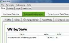
Well, here I did that. With some quick trial and error I found that a 17% max field weakening current resulted in the same unloaded RPM with the FOC as I was getting with the trapezoidal controller. This setting is in the Peripheral Configuration -> Advanced Motor tab.
Field Weakening Percentage.jpg

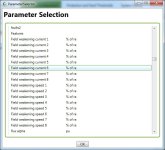
There is also have a table vs. RPM based field weakening option where you set the fielded weakening current as a function of your speed to have more control over this, but I didn't use that, just the automatic mode.
Field Weakening Table.jpg

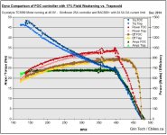
And the Dynamometer test results compared with the 48V trapezoidal experiment are just as we'd hope. At higher speeds, the two controllers behave quite similarly, with the same max RPM and the same slope of torque vs RPM, but as the motor is more heavily loaded then the FOC starts showing increasingly better efficiency and torque output for the same input power.
Comparison with Field Weakening.jpg

So it would seem there are no downsides to the automatic field weakening as far as having the best of both worlds, if you want the top end speed of trapezoid and the better loaded efficiency and smoothness of FOC.
 
What happens if you increase the field weakening value beyond that 17%, say 30% or whatever? Even faster top speed? Lower efficiency only at those top speeds or across the rest of the range? What are the advantages and downsides of doing that?
 
Definitely seems to have more improvement in the low speed end. Once it gets past current limiting, the curves are pretty close. Not huge, but significant.

I wonder if some of the theoretical advantage is getting lost in the stator iron? Maybe try messing with the PWM frequency.
 
bspalteh said:
What happens if you increase the field weakening value beyond that 17%, say 30% or whatever?

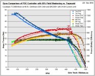
This is what happens, an even higher top speed! (from 440 rpm at 0%, now to 505 rpm at 30%)
Comparison with 30% Field Weakening.jpg

Even faster top speed? Lower efficiency only at those top speeds or across the rest of the range? What are the advantages and downsides of doing that?
Right now, I'm using the "automatic field weakening" mode which I understand only uses the field weakening at higher speeds where it has benefit, rather than having it do it across the board which doesn't make much sense.

Here I've got the 0%, 17%, and 30% field weakened graphs all super imposed on each other, and you can see that they all behave identical once they are below the speed where field weakening is required. So I would say there isn't really a downside for general operation, and the efficiency at the high speeds achieved by field weakening isn't all that bad either. In this example, where the trapezoidal controller topped out at ~475 rpm producing no more output, the FOC controller with 30% field weakening was still putting out 450 watts of power at about 78% system efficiency.


speedmd said:
What is causing the blip/ sweet spot just above 350 rpm.

That I really don't know. It's present on all the graphs that I've done with the FOC controller to a greater or lesser degree, but I don't see it on the tests with the infineon unit. On the last dyno I made a point to look closely at the behavior here and could definitely feel some oscillation and shaking in the dyno bench setup as it scanned through the 355-345 RPM band. So there is some kind of resonance at play.
 
Back
Top