Liquid Cooling MXUS 3000 using a Kit from Linukas

edventure

100 W
Joined
Feb 14, 2013
Messages
154
Location
Littleton, CO
I am in the process of installing an upgraded axle and copper cooling loops that were purchased from user Linukas. This kit is for a VS1 MXUS 3000 motor and will not work in the newer VS2 motor, but you may want to track what Linukas is up to, because he has talked about possibly creating a kit for the VS2 in the future. I posted an earlier thread under MXUS 3000 Hub Motor, but decided to start a new one here and have copied some of that information here. I was able to remove the original axle this evening and will post how I did this with some photos a bit later. Here is a link to the original thread where Linukas explained some of his mods. http://endless-sphere.com/forums/viewtopic.php?f=2&t=63142&hilit=Linukas&start=225

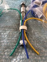
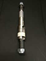
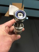
Ordered an upgraded axle from Linukas that has dual slots, one for heavier gauge wires and the other for the liquid cooling lines. He said this was a lower quality milling than another option he has, but he indicated he has used it on numerous bikes with no problems. It looks much better than the standard axle to me. I still need to have the side cover milled on one side to except the new larger 42mm OD x 30mm ID bearing. I have ordered and received new 12 gauge phase wires, from Turnigy that have a silicone jacket that is rated to 200C. Easily could have fit 10awg wire, but I did not see the reason based on the currents I will be running. Additionally I wanted the wires to have plenty of space to make assembling the motor easy. These are basically the same wires that come from the Lyen controller, so a good match and I was able to get the Blue, Yellow and Green to match the controller.

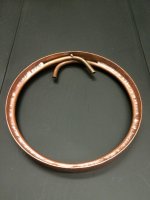
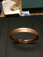
I also ordered the cooling lines TIG welded to the thin copper plate that will draw the heat away from the motor. The photos only show one loop, but Linukas actually sent two of these. I plan on placing Swagelok fittings with a barbed adapter to connect the actual soft lines to cut down on the possibility of leaking. I think the parts from Linukas were well worth what I paid for them. Placed some photos below if you're interested. Will update as things come together hopefully before January is out. Also, plan on taking the dimensions of the axle and drawing up a CAD file in Sketchup so I can share it here. Linukas had said he was ok with this in an earlier post. I want to thank Linukas for working with me on this and his willingness to answer my questions and get the parts to me. The water pump I plan on using will use minimal power and theoretically should not need to be turned on often, mainly when I am climbing hills that are 3 miles long where heat buildup becomes an issue. This should be very effective for removing heat from the motor in a short period of time. Once I get it working we will see.

Ed
 

Attachments

  • Space-12awg-wire.jpg
    Space-12awg-wire.jpg
    151.6 KB · Views: 6,954
  • Linukas-Axle.jpg
    Linukas-Axle.jpg
    47.8 KB · Views: 6,954
  • Dual-openings.jpg
    Dual-openings.jpg
    59.1 KB · Views: 6,954
  • Cooling-loop.jpg
    Cooling-loop.jpg
    83.6 KB · Views: 6,954
  • Cooling-loop-2.jpg
    Cooling-loop-2.jpg
    55.4 KB · Views: 6,954
Thanks for making a new thread on this. I really like this idea and may try it. This pics are great, looking forward to the outcome. Cool! :)
 
A few evenings ago I started to disassemble the motor and remove the stator. I used a method that user NeilP had advised me on in an earlier post and it worked very well again with minimal tools. I posted a link here to my earlier post where he had linked to a YouTube video he made. http://endless-sphere.com/forums/viewtopic.php?f=2&t=54647&start=25

I initially removed the C-Clip that holds the dust seal on the Brake side of the motor. This C-CLip was extremely difficult to remove since it is located in a recess. I ended up bending the C-clip and partially damaging the dust seal. I had to use a c-clip removal tool, flat head screw driver and Needle nose pliers to finegle it out of there. I also cut the heat shrink off the phase and hall wire cable where it enters the motor to make it easier to remove the side cover.
C-Clip Seal.jpg
Cut-Heatshrink.jpg
Motor-Disassembly.jpg
After using a 4mm Allen wrench to remove the bolts holding the side covers I only used a small mallet to completely remove the side covers.
Tool-Used.jpg
I was very impressed with the insides of the MXUS motor, seems quality control is better than the Crystalytes. I noticed there were thin spacers on both sides of the motor between the bearing and axle. There were two on the freewheel side and only one on the brake side. This could be due to lacking in the quality control, but at least they corrected for it.
Spacers-on-Freewheel-Side.jpgSpacer-Wire Exit Side.jpg

It is also interesting how they run the Phase and hall wires through the center of the axle and then it exits at an angle as it leaves the motor. You can see where the wires enter the axle on the photo above and where they axle on the photo below.
Wire Exit side-Stator.jpg
The next photo shows the Rotor parts including the magnets. Rotor-Components-Magnets.jpg

I will try posting more updates over the weekend and as things progress.

Ed
 
great thread, and aweseome work from Linukas.
what bearings will you use on the bigger axle side?
for longer lifespan i'll put 2 pcs 42/30/7 in the sidecover. they also will leave enough thread remaining for the brake rotor bolts..
 
Hey thats interesting. I note you're mounting it on a V1, not a v2.

It'd be interesting to compare toa v2 with side holdes drilled.
 
What is the advantage of using something like the mxus which requires cooling, so using something like the cro that doesn't unless you drive it really really hard ?.
 
great thread, and aweseome work from Linukas.
what bearings will you use on the bigger axle side?
for longer lifespan i'll put 2 pcs 42/30/7 in the sidecover. they also will leave enough thread remaining for the brake rotor bolts..

I looked into using two 7mm wide bearings, but this would actually end up in the Disk brake mounting hole area, it may not hit the bolts but the back of the screw holes, "that hold the disk break to the motor" would be exposed to the face of the bearing. The disk brake threaded holes are 16mm deep and the thickness of that bearing seat area is only around 22-23mm. So I will only use 1 30/42/7 bearing and a 17/35/10 on the freewheel side, which is the same as it is now. I finally ordered bearings last night from a company I have never used before, but I guess I will see. They are supposedly ABEC 5 quality bearings. I placed the links to Amazon where I ordered them through, but the company selling them is VXB bearings who can be found online at http://www.vxb.com Here is the link to the larger bearing, http://www.amazon.com/gp/product/B00J5OMF82/ref=oh_aui_detailpage_o00_s00?ie=UTF8&psc=1 and here is the link to the smaller bearing http://www.amazon.com/gp/product/B002BBJVDI/ref=oh_aui_detailpage_o01_s00?ie=UTF8&psc=1 I do not plan on milling the side cover until I receive the bearing so I can confirm the dimensions. Now I can't wait to get the bearings.

Hey thats interesting. I note you're mounting it on a V1, not a v2.

It'd be interesting to compare toa v2 with side holdes drilled.
I would be curious about this too. I am deciding right now whether I want to upgrade the Cycle analyst to a version 3 or just purchase a cheap digital thermometer that I can connect to the thermistor inside the motor. Either way I will try to post the results, and if anyone would like a specific test to be run let me know and I can try it. I can not compare to the version 2 since I do not have one, but I believe I will be able to dissipate much more heat and power. I will increase the battery voltage at some point, but that will be months after I get this done. What I can do is compare the cooling on to the cooling off on the same motor by just leaving the pump turned off that circulates the coolant.

What is the advantage of using something like the mxus which requires cooling, so using something like the cro that doesn't unless you drive it really really hard ?.

My personal thought is a motor with cooling is going to last longer and run more efficiently than one without cooling even if you're not driving it as hard is it can be driven. This is a challenge project for me and I think in the end I will have something that will last 10 times longer than my Clyte motor that blew after 1800 miles. Again, I am going to hear the same story, "I was driving it too hard and outside it's efficient range", but what I do know is when I pumped more amps into the old setup it would definitely pull harder on the hills around here. If I could keep it cool, the power I use for the pump may be partially paid back by the higher efficiency of the motor windings staying at a lower temperature. I know many people will say over-kill and not necessary, but I am having fun trying and you can all watch at my expense.

Sorry I have been a little slow with the updates hopefully a few more this evening. Have other priorities that pay the bills that need attending to first.

Ed
 
Hey Doc,

Thanks for posting your link here I had never seen it, but it gave me some ideas as I was reading through it. One thing though, I just spent an hour reading through it and get to the end and you never actually ran cooling fluid through it?? :? Early in the post your reasoning was in line with what I had been saying here, but then at the end you said that 120C on the stator coil didn't require the cooling fluid. Some magnet wire insulation is only good till 105C so at that temp your insulation could already be degrading. Did you already know the grade of the polymer coating on the magnet wire? Regardless it would still have been interesting to see if it worked better with the cooling fluid pumping. Do you plan on reviving the project, filling the loop and actively cooling it? I would be curious to see the results, especially since you pump much more power than I probably ever will, "maybe". Anyway, your work is beautiful great job. I am sure many like myself have gained valuable insight into taking your design and making it work on their system. I wish my motor was finished, but I can promise when mine is finished I will be cooling it.

Thanks,

Ed
 
agniusm said:
So much work on water cooling Stephane and not testing it is a serious crime :evil:

Yeah your are totally right :oops: :lol:

Well I WILL finish installing the pump and radiator as well. I am curious too to see the result. This might also be on my NYX bike as the 5403 motor will fit too.

I have used it for 2 years without putting a single drop of cooling I it and it never reached over 120-140 Celsius. With 293A 111v on the Kelly. Running it cooler will give more power as well since the winding resistance will decrease.

I run all my X5 motors to an average of 120-140 Celsius for several years without problem. This Is the temp limit I fixed myself
But I must limit power to all my X5 to not reach over 140 Celsius except for the 5403.
Curisously this is something I don’t need with the liquid cooled 5403 (that never tasted any liquid) it’s like all the added hardware inside for cooling are helping it to remain cooler.. but still without any liquid yet…

About temp.. I already have bring my DH comp with the 5303 to someone stupid that when he came back with the bike the motor was smoking!! and the displayed temp was... 260 Celsius!! :shock: but the motor color was not dark yet.. it was only darker orange wich is the color of the added varnish. but guess what.. that motor still work today! and the inductance and resistance of the winding did not changed ! what I keel is that it is a bit less efficient than before.. maybe the magnet lost a bit of gauss...

Doc
 
...but in electronics the cooler you run the more efficient you are, isn't it? I mean running 80C is always better than 120C?
 
Finally had some time to resize my photos and start placing them here with some explanations. Last Thursday evening I was finally able to determine a method that would work to remove the original axle. I will continue here what I had started above so you can see exactly what I have done and maybe what you shouldn't do if you plan on doing this same mod.

Placed a closeup of the Stator laminations. You can see a small amount of peeling back if you look close, but overall I think they are in good shape.

Stator-Laminations-Halls.jpg

Windings-Halls-Thermistor.jpg

Hall-Thermistor-Closeup.jpg

In this image you can see the original phase wire placement that I am preparing to cut. I cut the phase wires so some of the original colored wire was left on the so I can match them up easily when installing the new wire. You can see this in the photos below.

View attachment 10

Cut-Phase-Wires.jpg

I cut the cable tie and fiberglass insulation off the hall wires in preparation for cutting the hall wires. All the phase wires, hall wires and thermistor wires need to be cut so I can extract the main cable entering the motor from the axle before attempting to remove the axle. Couple photos below. I have made a diagram that I was going to convert into a simple schematic to show the layout of the hall wiring. While many of you may already know this setup, since it is basically the same between motors I just figured it would be good to document it here for the MXUS motor. I will post the schematic once I have time to make it.

Removed-Tie-Insulation.jpg

Cut-Hall-Wires.jpg

Next I removed the silicone sealant around where the cable entered the axle to make it easier to remove and then just pulled the Phase/Hall Cable from the axle in preparation for removing the axle. The cable has a very thick jacket on it which is nice because it makes it very robust and less prone to damage, too bad I won't be using this cable. I may try to find thicker shrink tubing so maybe I can create something similar. Photo of Cable Below.

Phase-Hall-Cable-Removed.jpg

I measured the distance that the axle extended from the stator flange on both sides of the motor so I could have a record in case needed later. I posted photos of the measurement below.

Brake-Side-Axle-Length .jpg

Freewheel-axle-length.jpg

This next photo shows the flange I was measuring from.

Measure-Closeup.jpg

Need to get some shut eye will try posting more in the coming days. My bearings should arrive by Friday, so hopefully have the Side cover machined by early next week. I have already been able to remove the old axle and will show this in my next posting.

Ed
 
Your doing a very methodical, detailed job and your efforts are appreciated.

A quick question as I couldn't quite tell from the photos-does the thermistor share the same ground as the halls?
 
Kent said:
Your doing a very methodical, detailed job and your efforts are appreciated.

A quick question as I couldn't quite tell from the photos-does the thermistor share the same ground as the halls?

Hi Kent,

Yes the thermistor does share the same ground as the halls. I actually created a schematic today thinking others may be able to use it in the future and also so I remember how to get it back together. I attached it below. Where each wire from the cable connects is listed in the drawing, even though I don't show the cable in the drawing. In one of my photos above you can almost see where all the +5V from the halls are soldered together and all the 0V from the halls and the thermistor are soldered together. They are covered by a piece of fiberglass Insulation. I will see if I can take a different shot later that shows this more clearly, but I think the schematic is the best option. If there is something not clear on it just let me know and I can change it.

Ed
 

Attachments

  • Hall Sensor Wiring.bmp
    385.1 KB · Views: 3,978
I am just continuing where I left off last. The axle can only be pressed out from one direction. When pressing it needs to be securely supported from the opposite side on a small flange that's only a bit larger than the axle itself. The night I did this it had taken me three attempts using 3 different setups until I finally found one that would work. I am hoping this part here will save someone much time in the future if they decide to go ahead and do this.

This first picture indicates the direction the axle needs to be pressed out from the stator.

Axle press direction.jpg

My first attempt I found an old broken vacuum pump housing that was no longer being used, but had the perfect OD to fit inside the stamped steel section of the motor. My thinking was, if I supported it across a larger suface area there would be less chance of damaging something. Well my thinking was entirely wrong :shock:. In addition I decided to try and create a video as I was starting to pump the press jack and was not paying close attention to what was happening. I could see the axle was moving down and thought it was actually being forced out, but instead the stamped steel section, "in the center of the stator" was beginning to bend. I immediately stopped using this method and ended up using the measurements I had taken earlier to move everything back into place. Placed a few photos below to show what I had attempted, "Don't do this!

View attachment 9

First-Attempt-inside.jpg

First-Attempt-Press.jpg

On my second attempt I decided to support the center smaller flange that surrounds the axle, but made the very stupid mistake of using a material that is not meant for this type of work, "PVC pipe" I did this in my late evening rush to just get the job done and not thinking it through a bit more" It could have turned out ugly if the tube would have splintered or exploded. At one point I had over 4000 psi pushing down on the stator and this tube and I noticed the tube was significantly bowing. It is obvious if the tube bows, the axle will never be pressed out due to force being placed on the axle in directions different from the direction it needs to move. I even made sure I squared the ends of the tube and filed them flat to be sure a parts of the tube were contacting the motor and base of the press at the same time. Big waste of time, and now I know. Placed a few photos below of this setup so you can get a good laugh.

2nd-attempt.jpg

2nd-Attempt-Press.jpg

View attachment 3

On my third attempt I had found another vacuum flange in my scrap instrument pile that had an opening that was of the right size, but the opening was recessed so the flange around the axle was not supported well. I went looking through my other scraps and found what looked like a short thick walled brass tube that was just a bit to large to fit in the recess on the vacuum flange. I have a crappy very old lather, but it was very capable of turning this pice down so that it would fill the recess and support the motor correctly. Ideally if I decided to do many of these motors I would find a thick walled brass tube like this that was about 20 CM long which would give enough space for the axle to be pressed into and then you would not need this extra vacuum flange I am using. This worked well but I had to get the press up over 5000 psi before finally I heard the snap of the axle breaking loose. Once it started moving the pressure dropped and it continued to be pushed out with less than a few hundred psi. I think the axle was hanging up on the key in the keyway of the stator. Photos below of what I explained here.

Fill-Spacer.jpg

View attachment 2

Final-Attempt-Press.jpg

Will post more later.
 
edventure said:
Finally had some time to resize my photos and start placing them here with some explanations. Last Thursday evening I was finally able to determine a method that would work to remove the original axle. I will continue here what I had started above so you can see exactly what I have done and maybe what you shouldn't do if you plan on doing this same mod.
Ed

For a little extra room, if you take out the 120 degree hall wires you'll get a little extra space, as some controllers like the Adaptto cant use the 120 degree halls anyway, so the wires are taking up space. When I re did a couple of my halls I removed the extra cables so I could fit some kevlar shieths around the cables to make them more durable as they come out he engine.
 
Hey.. Dont forget to NOT use these vaccum chamber equipment anymore!!! i guess that with that force on them they probably dont align pretty well now.. you'll need some indium or viton to fill the gap !!!

Last time i used a 20T press to remove the axel of my 5403, the axel bent under that pressure! I was applying force to the wrong way :roll: :lol:

My best advices would be to not press on the axel threaded part.. and only do it on the lower part that is larger sometime with the help of a steel tube extension...

btw that press with 3 threaded rods abd sproket moved by a common chain is a nice simple design! Is it in your lab or at the university?

Doc
 
Doctorbass said:
Hey.. Dont forget to NOT use these vaccum chamber equipment anymore!!! i guess that with that force on them they probably dont align pretty well now.. you'll need some indium or viton to fill the gap !!!

Last time i used a 20T press to remove the axel of my 5403, the axel bent under that pressure! I was applying force to the wrong way :roll: :lol:

My best advices would be to not press on the axel threaded part.. and only do it on the lower part that is larger sometime with the help of a steel tube extension...

btw that press with 3 threaded rods abd sproket moved by a common chain is a nice simple design! Is it in your lab or at the university?

Doc

Hey Doc,

Don't tell anybody about the vacuum equipment. I run a repair shop at the university, and have a junk pile of miscellaneous old equipment. I hang on to many items in case someone comes to me and wants to build something. I can sometimes pull the parts together without requiring much money. I think the vacuum parts will still be fine, since most of the pressure was placed across a fairly large surface area and the sealing surfaces are internal on both the oring sealed parts and the conflats. Had to state this to make myself feel better :) .

Regarding pressing the axle, I have already removed it. Ideally, "if I decide to do this in the future I will find a long think walled metal tube similar to the brass piece I had cut to fit in side the vacuum flange, but much longer. This is all you should need if it is the right length and cut straight.

The press is in one of the labs in the university. It has not been used for about 3 to 4 years now, but we have still hung onto it and I am glad we did. We used to use it for creating KBr, Potasium Bromide pellets for calibration and testing of a lab instrument, but this is no longer required. The press is supper simple, but very effective and has a very tall opening for large pieces. I think it is more than 40 years old, but still works like a champ.

I will see what I do when I am ready to press the new axle into place.

Ed
 
For a little extra room, if you take out the 120 degree hall wires you'll get a little extra space, as some controllers like the Adaptto cant use the 120 degree halls anyway, so the wires are taking up space. When I re did a couple of my halls I removed the extra cables so I could fit some kevlar shieths around the cables to make them more durable as they come out he engine.

Hi Crea2k,

Thanks for the advice, just curious where you purchased the Kevlar Sheaths, since I will be needing some replacement insulation once I reassemble everything.

Thanks,

Ed
 
Continuing on my progress from the earlier post.

By using the Vacuum flange in the last pic of the last post I was able to push the axle free after getting up close to 5000 psi of pressure. When it finally broke loose it made a cracking sound and then continued to easily slide out the rest of the way. Some photos below after the axle was removed and some comparison photos of the new and old axles next to each other.

Original-axle-removed.jpg

Photo below was of the stator minus the axle. You can easily see the keyway where I think the old axle was getting hung up while trying to press it out. At this point I was feeling very confident I can make this all come together and work. Of course this feeling will change right after I hit my next problem.

Stator-No-Axle.jpg

I placed the new axle inside the stator to just get an idea of the fit, and everything looks pretty good so far. The channels for the wiring and liquid tubing are looking very spacious.

Initial-placement-new-axle.jpg

The next 3 photos compare the Old Axle to the New one.

Axle-Compare-1.jpg

Axle-Compare-2.jpg


ED
 
Latest Update. I received my two new ceramic bearings this week from VXB Bearing in California. I gave the large bearing, axle and the side cover with the brake mount to a machinist today so he can mill the larger opening for the new bearing. Keeping my fingers crossed it turns out well since I have not used this machinist before. Hope to have the cover back sometime this week and will post pictures once I do. I now need to order some thermal adhesive to mount the cooling loops inside the stator and decide if I want to sand off the paint on the stator before attaching the cooling loops to give a better thermal contact with the stator metal. Any input here would be appreciated. I will order the thermal adhesive, replacement fiberglass sheaths or maybe kevlar and any other miscellaneous items I may need this week so hopefully I can complete the reassembly in the coming two weeks. Will continue to post as things come together however slow it may be.
 
thanks for sharing some pics^^ whats the size of the bearings you will use?
I will install 42/30/7 2pcs for longer lifesspan. They leave enough thread left for brake rotor srews after machining the sidecover. Ceramic would be awesome, but from what i have seen they are very expensive so i ordered FAG / SKF "RS" bearings.
 
Back
Top